Heating and hot water supply system

A technology for supplying hot water and heat medium, which is applied in heating systems, hot water central heating systems, and household heating, etc. It can solve the problem of not being able to supply hot water and heating at the same time, detrimental to comfort, and lowering room temperature, etc. question

Active Publication Date: 2015-02-11
MITSUBISHI ELECTRIC CORP
View PDF6 Cites 3 Cited by
  • Summary
  • Abstract
  • Description
  • Claims
  • Application Information

AI Technical Summary

Problems solved by technology

Therefore, the hot water supply function and the heating function cannot be realized at the same time, and as a result, there is a problem that the room temperature decreases during the hot water supply, which impairs comfort.

Method used


Image

  • Heating and hot water supply system
  • Heating and hot water supply system
  • Heating and hot water supply system

Examples


Embodiment approach 1

[0019] [Structure of Embodiment 1]

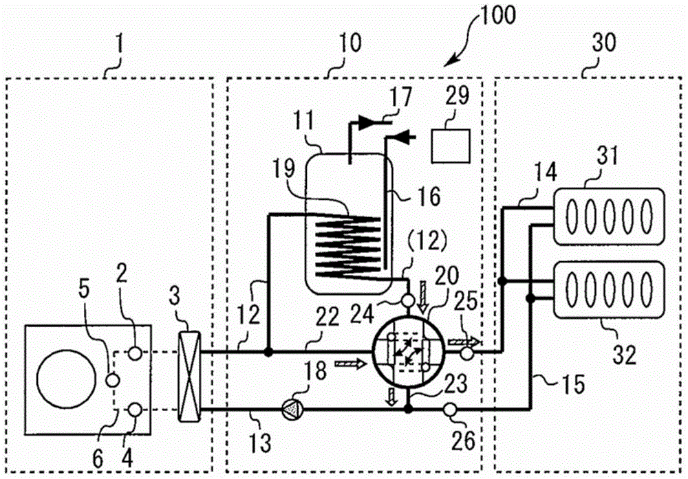
[0020] figure 1 It is a circuit configuration diagram of the heating and hot water supply system 100 according to Embodiment 1 of the present invention. figure 1 The shown heating and hot water supply system 100 includes: a heat pump unit 1 equipped with a refrigerant circuit of a vapor compression refrigeration cycle (heat pump cycle); The water storage tank unit 10; and the heating unit 30 which is constituted by a part of the heating circulation circuit and heats the room.

[0021] The heat pump unit 1 and the hot water storage tank unit 10 are connected via heat medium pipes 12 and 13 . The hot water storage tank unit 10 is connected to the heating unit 30 via heat medium pipes 14 and 15 . In addition, the hot water storage tank unit 10 is connected to a hot water supply pipe 17 connected to a hot water supply terminal (such as a faucet in a kitchen or a toilet) and a water supply pipe 16 for supplying water from a water source such ...

Embodiment approach 2

[0046] [Structure of Embodiment 2]

[0047] Figure 6 It is a circuit configuration diagram of a heating and hot water supply system 200 according to Embodiment 2 of the present invention. Figure 6 The heating and hot water system 200 shown except figure 1 In addition to the configuration of the shown heating and hot water supply system 100 , a heat medium pipe 27 connecting the discharge side of the heat medium pump 18 of the heat medium pipe 13 to the heat medium pipe 14 is provided. A flow rate adjustment valve 28 functioning as a third flow rate adjustment mechanism for adjusting the flow rate of the heat medium flowing through the heat medium pipe 27 is provided midway in the heat medium pipe 27 . As the flow rate adjustment valve 28, for example, a valve capable of fine flow rate adjustment such as a spherical valve or a butterfly valve is preferable.

[0048] [Operation of Embodiment 2]

[0049] The heating and hot water supply system 200 is based on the heating re...


PUM


Abstract

There is provided a heating and hot water supply system capable of simultaneously achieving a hot water supply request and a heating request. The heating and hot water supply system includes: a heat pump unit 1 that heats a heat medium; a hot water supply heat exchanger 19 that performs heat exchange between the heat medium and water in a hot water storage tank 11; heating heat exchangers 31, 32 that heat an inside of a room using the heat medium; a heat medium pump 18; heat medium pipes 12 to 15 that connect a discharge side of the pump 18, the heat pump unit 1, the hot water supply heat exchanger 19, the heating heat exchangers 31, 32, and a suction side of the pump 18 in order; a bypass pipe 22 that bypasses the hot water supply heat exchanger 19 from the heat medium pipe; a bypass pipe 23 that bypasses the heating heat exchangers 31, 32 from the heat medium pipe; a four-way valve 20 that regulates flow distribution of the heat medium between the hot water supply heat exchanger 19 and the pipe 22, and between the heating heat exchangers 31, 32 and the pipe 23; and a control unit 29 for controlling the four-way valve 20 in accordance with a hot water supply request and a heating request.

Description

technical field [0001] The present invention relates to a heating and hot water supply system, and in particular to a heating and hot water supply system that uses hot water heated by a heat pump as a medium to implement hot water supply and heating. Background technique [0002] Conventionally, for example, Patent Document 1 discloses a heating and hot water supply system, which has a heating system that realizes the heating function by circulating hot water heated by a heating mechanism to a heating terminal, A hot water supply system that heats the water in the hot water storage tank by circulating water to the heat exchanger in the hot water storage tank. Specifically, this heating and hot water supply system includes a circuit for circulating hot water heated by a heat pump unit to a heating terminal, and a circuit for circulating hot water to a heat exchanger in a hot water storage tank by using the heating terminal as a bypass. By switching the three-way valve provid...

Claims


Application Information

Patent Timeline
Patent Type & Authority Applications(China)
IPC IPC(8): F24H4/02
CPCF24D19/1021Y02B30/12F24D3/105F24D2220/0242F24D3/082F24D19/1024F24D19/1072F24D3/08F24D19/1039F24D3/18
Inventor 南迫博和
Owner MITSUBISHI ELECTRIC CORP
Why Eureka
Try Eureka