Plate packaging and drawing forming device and forming method
A sheet and cladding technology, applied in the field of sheet wrapping forming devices, can solve problems such as the height of easily broken forming, achieve the effects of precise manufacturing, improving the quality of deep drawing and reducing the total energy
- Summary
- Abstract
- Description
- Claims
- Application Information
AI Technical Summary
Problems solved by technology
Method used
Image
Examples
Embodiment 1
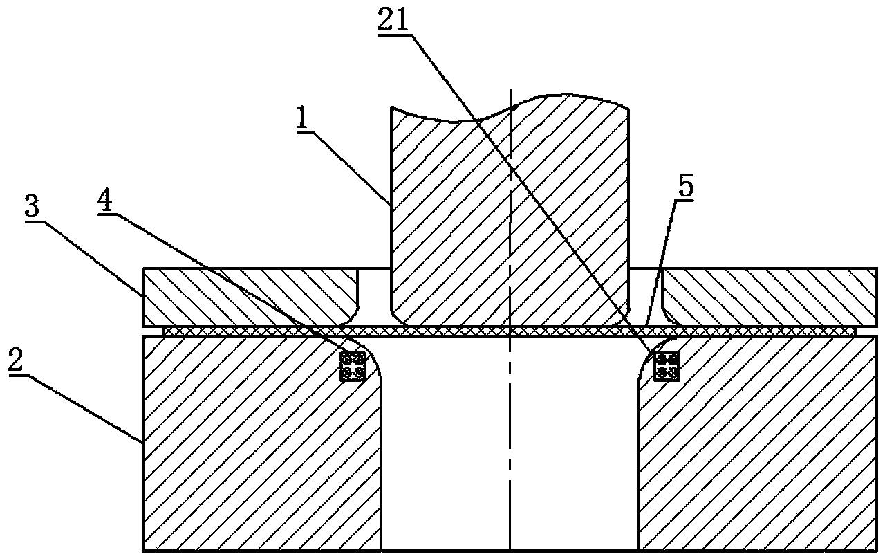
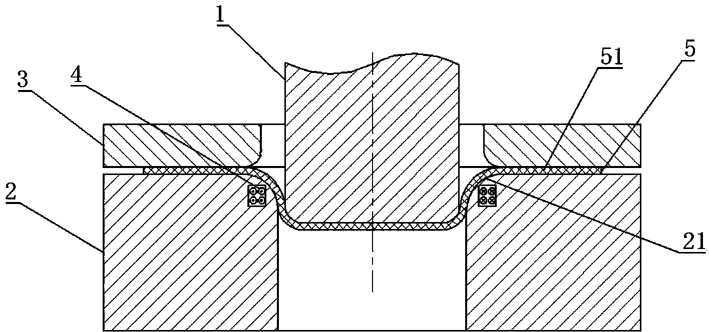
[0062] refer to Figure 1a ~ Figure 1h , a sheet material wrapping forming device, including a punch 1, a die 2, and a blank holder 3 for cooperating with the top surface of the die 2 to press a sheet 5, and the sheet 5 is drawn and deformed to produce a flange portion 51 , the flange portion 51 refers to the horizontal undeformed annular portion on the plate 5 , and the function of the blank holder 3 thereafter is mainly to press the flange portion 51 of the plate 5 .
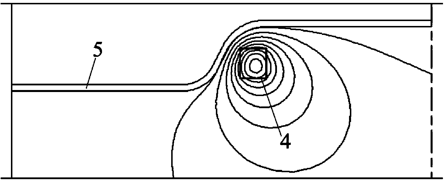
[0063] The blank holder 3 is located above the die 2, and the die 2 is provided with a rounded corner 21 that is convenient for drawing the plate 5, and the die 2 is equipped with an anti-expansion coil 4 at a position corresponding to the rounded corner 21. , as a preference of this embodiment, the anti-expansion coil 4 is a concentric coil, and the anti-expansion coil 4 is used to make the area of the plate 5 that slides to the fillet 21 of the die 2 move away from the fillet 21 after being energized Bend...
Embodiment 2
[0071] refer to Figure 2a ~ Figure 2h , the difference from Example 1 is that on the basis of Example 1, upper close-packed coils are respectively provided on the blank holder 3 and the die 2 at positions corresponding to the flange portion 51 of the plate 5 6 and the lower close-packed coil 7, as a preferred embodiment of this embodiment, the upper close-packed coil 6 and the lower close-packed coil 7 are concentric coils, and the upper close-packed coil 6 and the lower close-packed coil 7 are under the action of pulse current Lateral electromagnetic force is generated to push the flange portion 51 of the plate 5 toward the punch 1 .
[0072] The deep drawing forming method of a kind of plate wrapping forming device described in embodiment 2 is as follows:
[0073] Such as Figure 2a As shown, firstly, the plate 5 to be formed is placed between the blank holder 3 and the die 2 . The upper close-packed coils 6 and the lower close-packed coils 7 are arranged in the grooves ...
Embodiment 3
[0075] refer to Figure 3a ~ Figure 3h The difference between embodiment 3 and embodiment 2 is that, on the basis of embodiment 2, a side push coil 8 is arranged between the blank holder 3 and the die 2, as a preferred embodiment of this embodiment , the side push coil 8 is a concentric coil, and the side push coil 8 surrounds the flange portion 51 of the plate 5, and the side push coil 8 generates side thrust under the action of a pulse current to apply a lateral force to the outer edge of the flange portion 51 of the plate 5. The electromagnetic force pushes the flange portion 51 of the plate 5 toward the punch 1 .
[0076] The deep drawing forming method of a kind of sheet material wrapping forming device described in embodiment 3 is as follows:
[0077] Such as Figure 3a As shown, firstly, the plate 5 to be formed is placed between the blank holder 3 and the die 2 . The upper close-packed coils 6 , the lower close-packed coils 7 and the side push coils 8 are arranged in ...
PUM
 Abstract
Description
Claims
Application Information
 - R&D
- Intellectual Property
- Life Sciences
- Materials
- Tech Scout
- Unparalleled Data Quality
- Higher Quality Content
- 60% Fewer Hallucinations
Browse by: Latest US Patents, China's latest patents, Technical Efficacy Thesaurus, Application Domain, Technology Topic, Popular Technical Reports.
© 2025 PatSnap. All rights reserved.Legal|Privacy policy|Modern Slavery Act Transparency Statement|Sitemap|About US| Contact US: help@patsnap.com


