
Device for connecting the ends of pipes made of steel by means of an orbital welding process

A technology for orbital welding and welding parts, which is applied in the field of end devices and can solve the problems of high cost and complicated welding process.

Active Publication Date: 2015-02-18
SALZGITTER MANNESMANN LINE PIPE
View PDF6 Cites 10 Cited by
  • Summary
  • Abstract
  • Description
  • Claims
  • Application Information

AI Technical Summary

Problems solved by technology

As a result, the device becomes very heavy and can be used flexibly in place only with high outlay
[0006] Furthermore, the procedure of the welding process is complex, in which the pipe ends have to be pushed into the device and centered and then the welded pipe has to be drawn out of the device according to its length
[0007] In summary, it has been established that, according to the prior art, there is currently no industrially applicable rail guidance system that is optimally compatible with the requirements in terms of quality and economy of orbital welding

Method used


Image

  • Device for connecting the ends of pipes made of steel by means of an orbital welding process
  • Device for connecting the ends of pipes made of steel by means of an orbital welding process
  • Device for connecting the ends of pipes made of steel by means of an orbital welding process

Examples


Embodiment Construction

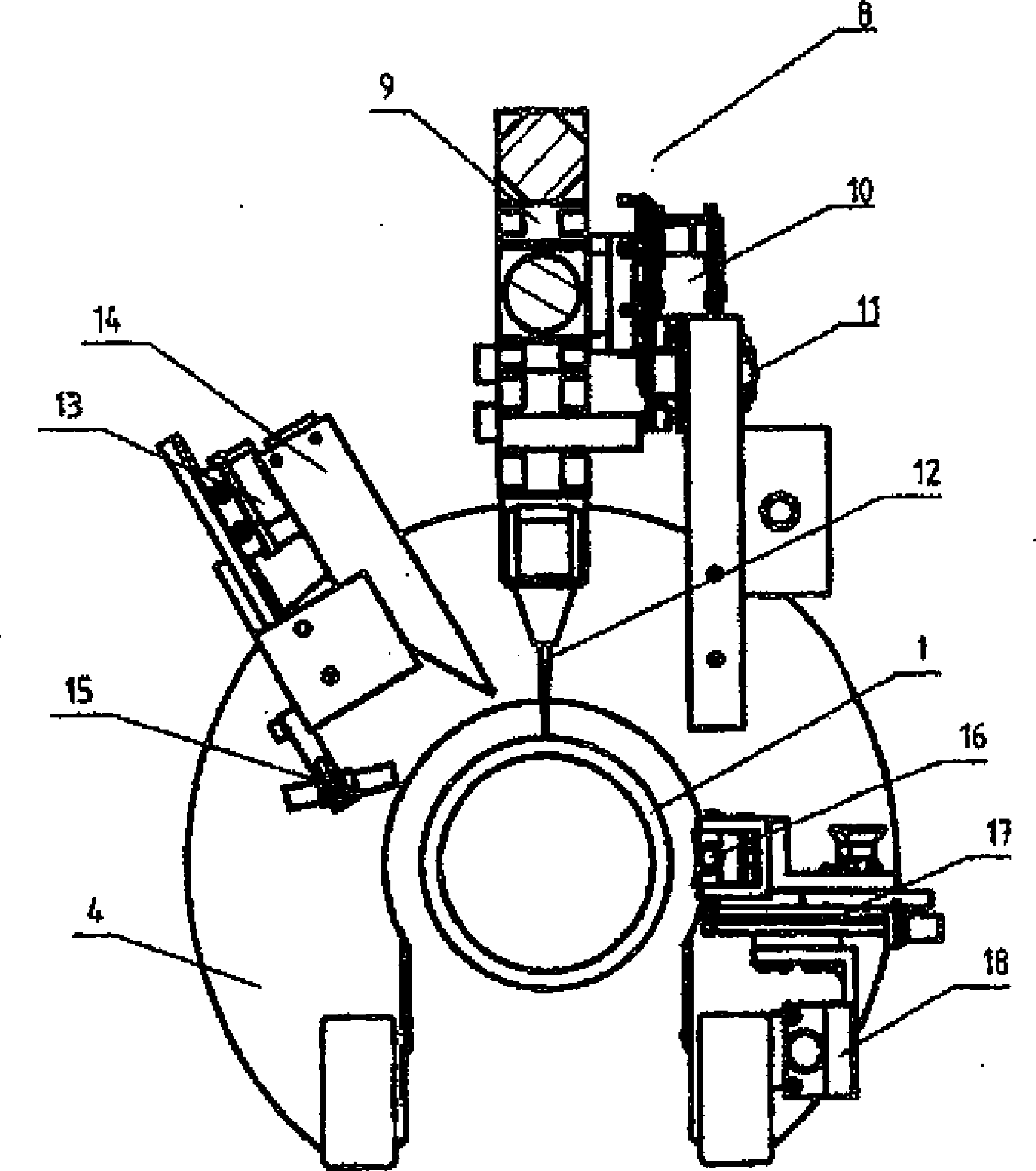
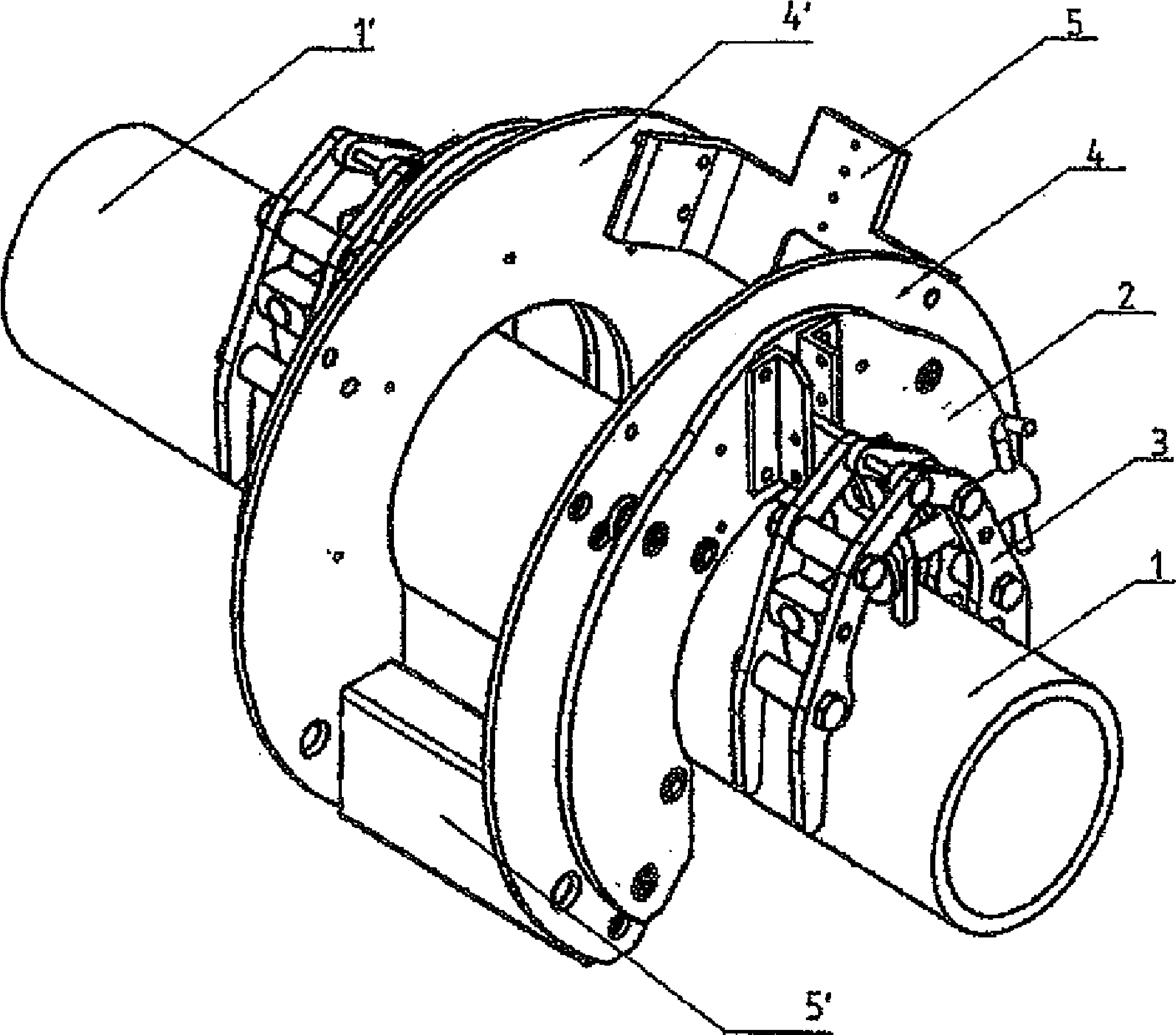
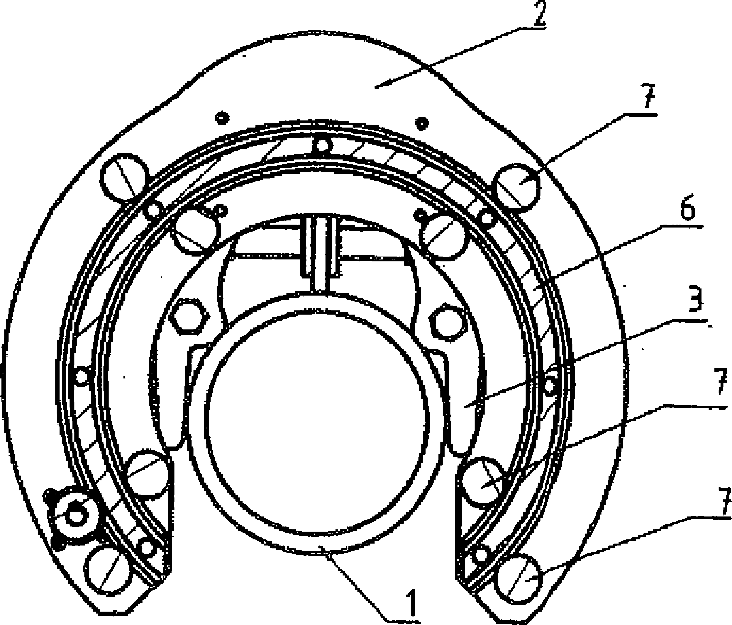
[0025] figure 1 The basic structure of the device according to the invention is described. It consists of two annular guide base plates 2 provided with radial openings in order to be able to place them on the pipes 1 , 1 ′ to be joined. The diameter of the inner ring is greater than the diameter of the tubes 1 , 1 ′ to be welded, so that the centering of the welding and testing tool can be precisely corrected by radial play. In order to fix the device on the ends of the tubes 1, 1', clamping elements 3 are mounted on the outside of the guide base plates 2 facing away from the welding joint, with which the two guide base plates 2 are each connected to a tube end. Clamped by clamping element 3 .

[0026] On the inner side of the guide base plate 2 facing the weld joint, a circular swivel hoop 4, 4', which is likewise provided with radial openings, is guided in a rotationally mounted manner, so that it can be carried out around the pipe 1, 1' along the Guide the circular motio...


PUM

PropertyMeasurementUnit
thicknessaaaaaaaaaa

Abstract

The invention relates to a device for connecting the ends of pipes, which are already aligned and tack-welded and which are made of steel in particular, by means of an orbital welding process using a welding joint which is formed by the pipe ends and using tools which can be moved about the welding joint in an orbital manner for welding and checking the welding seam. The device consists of guide base plates which can be placed on both sides at each pipe end in the region of the welding point and which can be rigidly clamped to said pipe ends. The guide base plates centrally have a circular recess with a radial opening for the feed-through of the pipes to be welded and for centrally receiving said pipes in the recess. The guide base plates comprise clamping elements for clamping the guide base plates to the pipe ends, said clamping elements being rigidly connected to each guide base plate face facing away from the welding joint, and a frame for receiving the welding and checking tools, said frame being rotatably mounted between the guide base plates on the inner faces facing the welding joint and being centrally pivotal about the pipe ends by at least 360°.

Description

technical field [0001] The invention relates to a device for joining ends of steel pipes by means of orbital welding according to the preamble of claim 1 . [0002] The invention relates in particular to pipes which can have, for example, a wall thickness of 2 to 20 mm and a diameter of 60 to 1600 mm and which are connected to one another by means of different welding methods, such as laser beam welding, laser-arc welding with hybrid technology or arc welding. Welding of road pipes. The lower tube is understood not only as an annular tube but also as a hollow profile with different cross-sections. Background technique [0003] Welding pipes using orbital technology is generally known, for example, from DE 103 34 446 A1. Herein, an orbital welding device for joining two pipe ends is disclosed, wherein the orbital welding device is placed on and clamped to a first pipe end and the second pipe end is brought to the second pipe end. In the welding position before the end of a...

Claims


Application Information

Patent Timeline
Patent Type & Authority Applications(China)
IPC IPC(8): B23K37/053B23K31/02B23K9/028B23K26/28
CPCB23K26/285B23K2203/04B23K9/0286B23K9/1274B23K31/027B23K2201/06B23K9/23B23K2101/06B23K2103/04B23K26/282B23K26/348B23K37/053B23K31/02B23K26/103B23K31/125G01N29/265G01N2291/0289G01N2291/267
Inventor H-J.科克斯J.温克尔斯S.凯特尔J.诺伊贝特S.鲁德
Owner SALZGITTER MANNESMANN LINE PIPE
Learn More