A toy that can hold a toy object
A toy and clamping technology, applied in the field of children's toys, to achieve the effect of enhancing competition awareness, increasing fun, and novel gameplay
- Summary
- Abstract
- Description
- Claims
- Application Information
AI Technical Summary
Problems solved by technology
Method used
Image

Examples
Embodiment 1
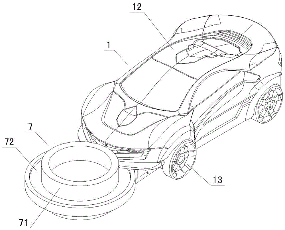
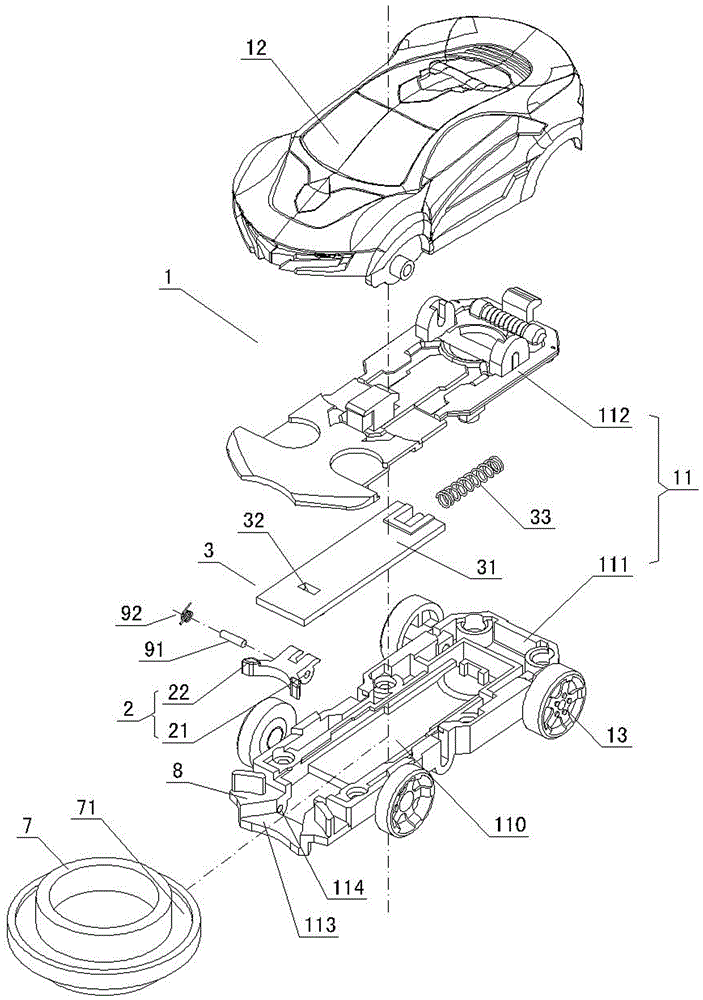
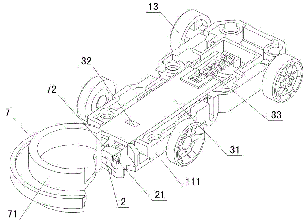
[0023] Such as Figure 1 to Figure 3 As shown, the toy body 1 of this embodiment is in the form of a toy car. The toy car includes a chassis 11, a car shell 12 and wheels 13. The clamping structure of this embodiment is arranged at the front end of the chassis 11. The clamping The structure includes a clamping chamber 8 that can accommodate toys. The chassis 11 of this embodiment includes a base 111 and a cover 112. A space 110 is left between the base 111 and the cover 112. The front end of the space 110 part forms a clamping cavity 8, the opening end of the clamping cavity 8 faces to the front of the toy body 1, by pushing the toy body 1 to the toy object 7, the toy object 7 enters the clamping cavity 8 and triggers the clamping part to realize Clamp the toy object 7; the clamping part of this embodiment is an elastic seesaw 2 protruding from the lower inner side of the clamping chamber 8, and a concave position 113 is provided at the front end of the base 111. The elastic s...
Embodiment 2
[0025] Such as Figure 4 and Figure 5 As shown, the toy body 1 of this embodiment is in the form of a toy car, and the clamping structure of this embodiment also includes a clamping cavity 8. The elastic protrusion 4 includes a card seat 41, a spring 42 and a boss 43, wherein the card seat 41 is integrally formed with the clamping cavity 8, the spring 42 is installed in the card seat 41, and the boss 43 is inserted into the card seat 41 and Part of it extends out of the deck 41. When the toy 7 enters the clamping cavity 8, the edge of the toy 7 squeezes the protrusion 43 to shrink inwardly. Under action, the toy object 7 is reset and snapped into the groove 72 of the toy object 7 , thereby realizing fixing the toy object 7 in the clamping cavity 8 .
Embodiment 3
[0027] Such as Figure 6 to Figure 8As shown, the clamping structure of this embodiment includes clamping claws 5 located on both sides of the front of the toy body 1 and a clamp located in the middle of the front of the toy body 1 for unlocking the clamping claws 5 so that the clamping claws 5 can be rotated forward. Touch panel 6, the toy body 1 of this embodiment is in the form of a toy car, and the toy car includes a chassis 11, a car shell 12 and wheels 13. The clamping structure of this embodiment is arranged at the front end of the chassis 11. The specific connection mode of the clamping claw 5 is that the clamping claw 5 and the front corner of the chassis 11 are provided with shaft holes, and the connection is realized by inserting the rotating shaft 91 into the shaft hole, and the rotating shaft 91 is sleeved with a torsion spring 92 , the clamping claw 5 is turned forward under the elastic force of the torsion spring 92 to encircle the toy object 7 after the clampin...
PUM
 Abstract
Description
Claims
Application Information