Automatic elevator guide rail painting line

A technology for elevator guide rails and paint lines, which is applied to spraying devices, coatings, and devices for coating liquid on the surface, etc., which can solve the problems of large influence on the quality of T-shaped guide rail painting, heavy labor workload, and uneven paint thickness and other problems, to achieve the effect of good painting effect, high painting efficiency, convenient installation and maintenance

Active Publication Date: 2015-02-25
张家港市张运机械制造有限公司
View PDF7 Cites 10 Cited by
  • Summary
  • Abstract
  • Description
  • Claims
  • Application Information

AI Technical Summary

Problems solved by technology

The traditional painting method is manual painting, that is, first manually turn the T-shaped guide rail placed in a ⊥ shape 180° to a T-shaped place, so that the fixed arm of the T-shaped guide rail is placed upwards, and then manually paint the T-shaped guide rail with a paint brush. The upper surface and bottom surface of the guide rail fixed arm, as well as the left and right sides of the guide arm connecting arm, are painted. After the painting is completed, the T-shaped guide rail is manually turned 180° to place in the initial ⊥ shape; this manual painting The operation method not only requires a lot of labor, but also the painting quality of the T-shaped guide rail is greatly affected by the level of worker proficiency, and it is easy to have quality problems such as uneven painting thickness.

Method used


Image

  • Automatic elevator guide rail painting line
  • Automatic elevator guide rail painting line
  • Automatic elevator guide rail painting line

Examples


Embodiment Construction

[0015] The present invention will be further described below with reference to the accompanying drawings and specific embodiments.

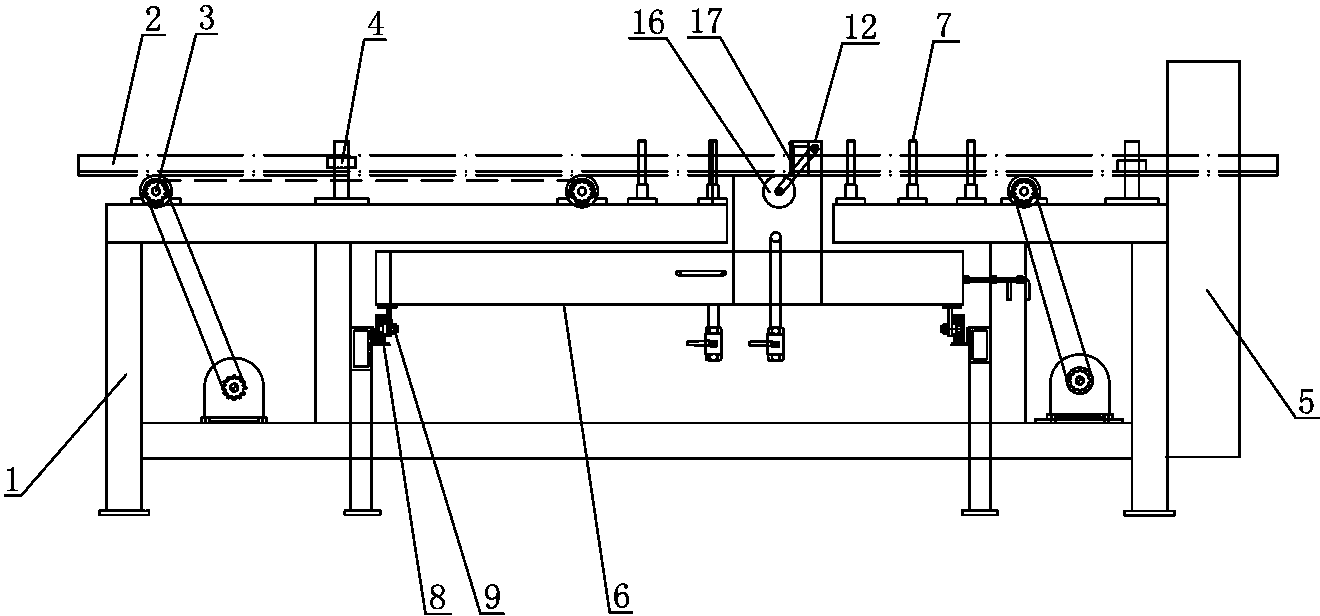
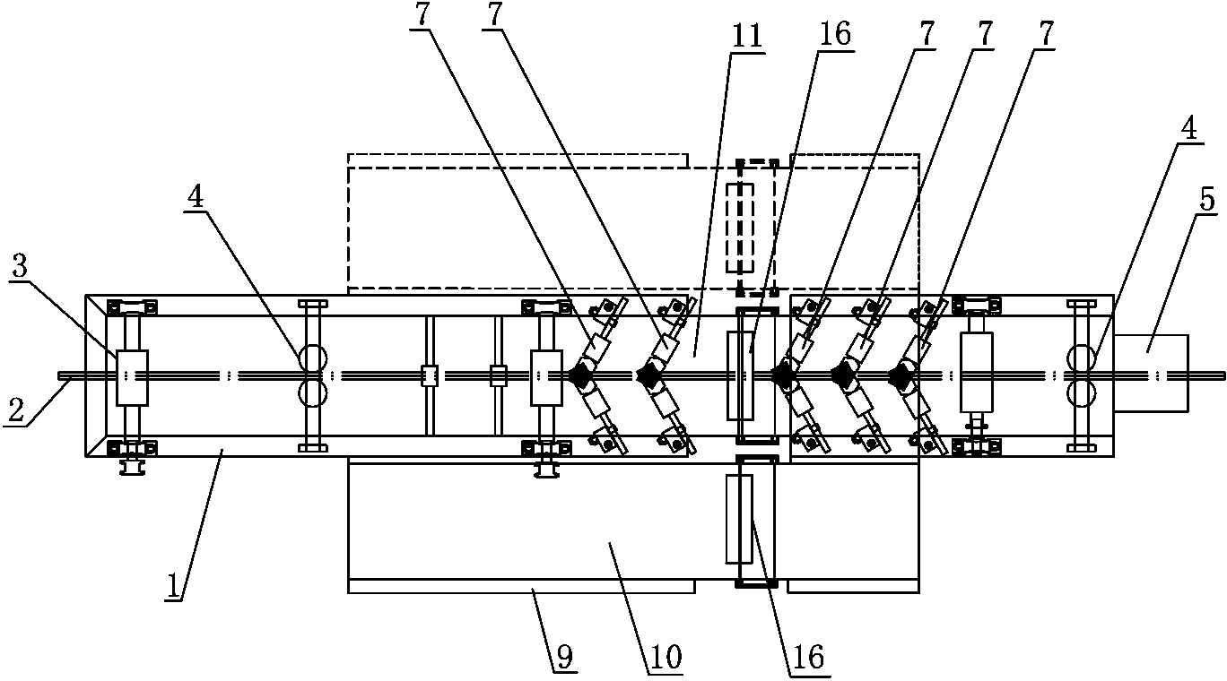
[0016] like figure 1 , figure 2 , Figure 4 , Figure 5 As shown, the described elevator guide rail automatic paint line comprises: a frame 1, in the frame 1, a plurality of conveying rollers 3 for horizontally and horizontally carrying the elevator guide rails 2 placed in a ⊥ shape and guiding the elevator guide rails are arranged at intervals 3. The centering guide mechanism 4 for centering and conveying, in the frame 1 along the conveying direction of the elevator guide rail 2, a paint spraying mechanism 5 and a paint brushing device are sequentially arranged at intervals, and the paint spraying mechanism 5 can spray paint to the guide arm of the elevator guide rail. The connecting part, the paint brushing device comprises a bottom surface paint rolling mechanism 6 arranged in the frame along the conveying direction of the elevator guide r...


PUM


Abstract

The invention discloses an automatic elevator guide rail painting line. The automatic elevator guide rail painting line comprises conveying rollers and centering guide mechanisms which are both arranged in a rack; a paint spraying mechanism and a paint brushing device are orderly arranged in the rack in the conveying direction of the elevator guide rail; the paint brushing device comprises a bottom surface paint rolling mechanism and a surface paint brushing mechanism; the bottom surface paint rolling mechanism is so structured that a horizontal and longitudinal moving rail is arranged at the bottom of the rack, a longitudinal moving support is arranged on the horizontal and longitudinal moving rail, at least two paint tanks are formed in the longitudinal moving support, mounting supports are arranged on the two sides of each paint tank, respectively, a first rotating shaft is supported between every two mounting supports, connecting rods are arranged on the shaft bodies on the two sides of the first rotating shaft, respectively, a second rotating shaft is supported between every two connecting rods, a paint brushing roller is mounted on the second rotating shaft, the lower part of each paint brushing roller is soaked in the paint in the corresponding paint tank, each connecting rod is connected with the mounting supports by use of elastic return elements, the paint brushing rollers always have the trend of clinging to the bottom surface of an elevator guide rail fixing arm upwards under the action of the elastic force of the elastic return elements. The automatic elevator guide rail painting line has the advantage of high paint brushing efficiency.

Description

technical field [0001] The present invention relates to an elevator guide rail automatic paint line. Background technique [0002] The bridge car of the van elevator realizes smooth vertical lifting by sliding up and down along the T-shaped elevator guide rail (referred to as "T-shaped guide rail"). The structure of the T-type guide rail is: including a guide rail body with a T-shaped cross-section. The guide rail body is composed of a fixed arm and a guide arm perpendicular to the middle of the fixed arm. The guide arm includes a guide arm connecting part and a guide arm guide part. The guide arm passes through The connecting part of the guide arm is connected and fixed with the fixed arm. When the T-shaped guide rail is installed and used, the fixed arm of the T-shaped guide rail is fixed to the building, so that the guide arm guide part of the T-shaped guide rail guide arm is slidingly matched with the car. During the production and use of the T-type guide rail, it need...

Claims


Application Information

Patent Timeline
Patent Type & Authority Applications(China)
IPC IPC(8): B05C5/00B05C11/02B05C11/10
CPCB05C1/06B05B13/00
Inventor 王佳斌夏家兵薛跃夏军王荣刘建忠卞文龙
Owner 张家港市张运机械制造有限公司
Why Eureka
Try Eureka