

Ground rod for power supply line
A technology for power supply lines and grounding rods, which is applied in the direction of circuits, conductive connections, and wire-wrapped connectors. It can solve problems such as insufficient tightness of power supply cables, affecting the service life of grounding rods, and affecting the grounding effect, so as to reduce the rate of broken strands , Guarantee the effect of grounding and improve the service life
- Summary
- Abstract
- Description
- Claims
- Application Information
AI Technical Summary
Problems solved by technology
Method used
Image

Examples
Embodiment 1)
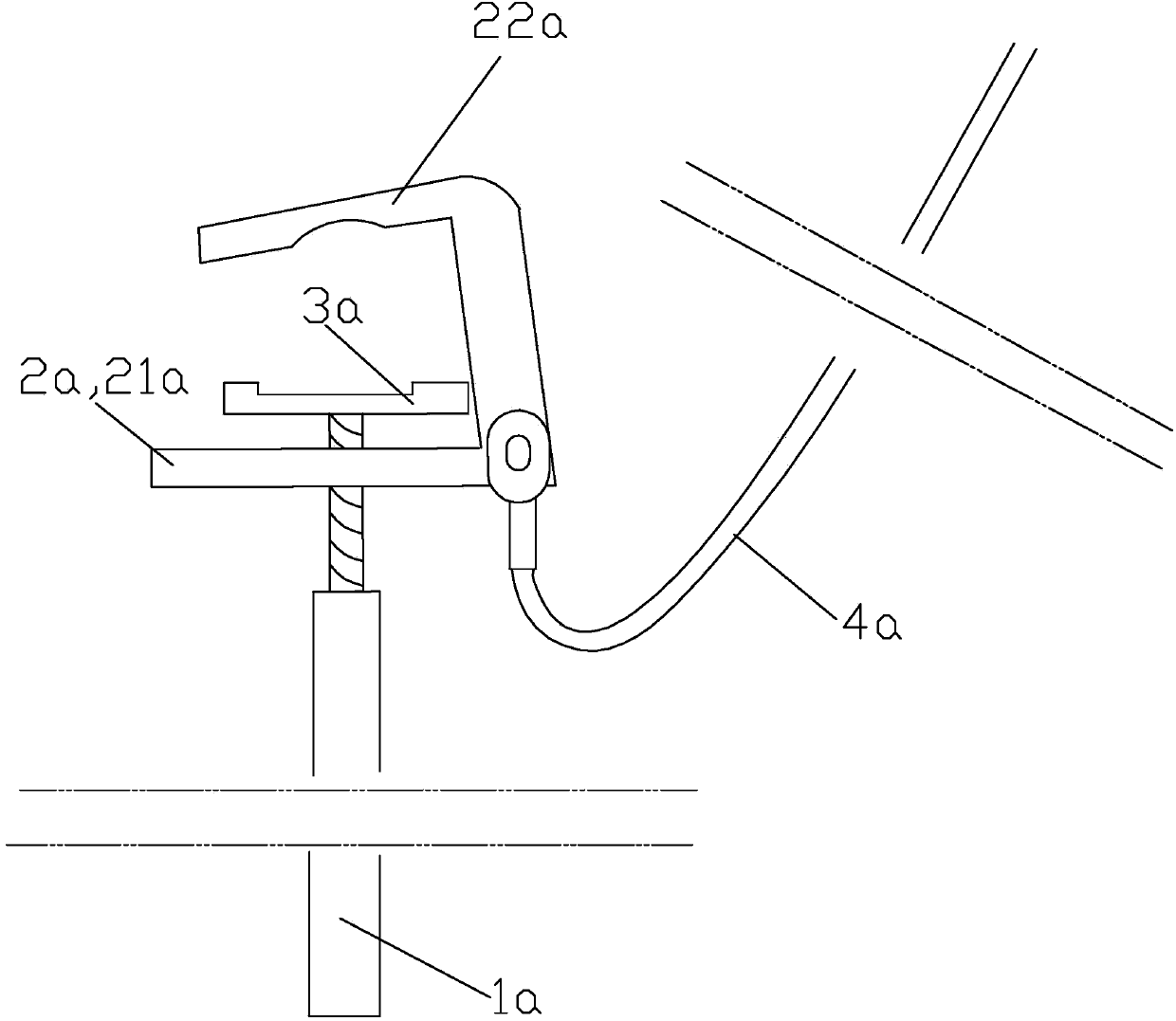
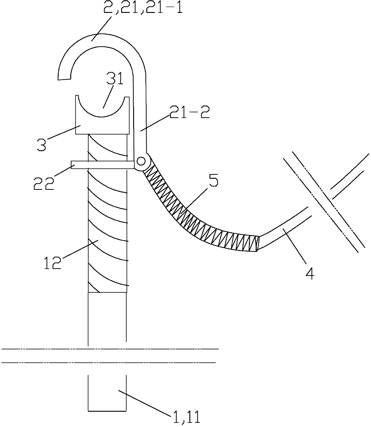
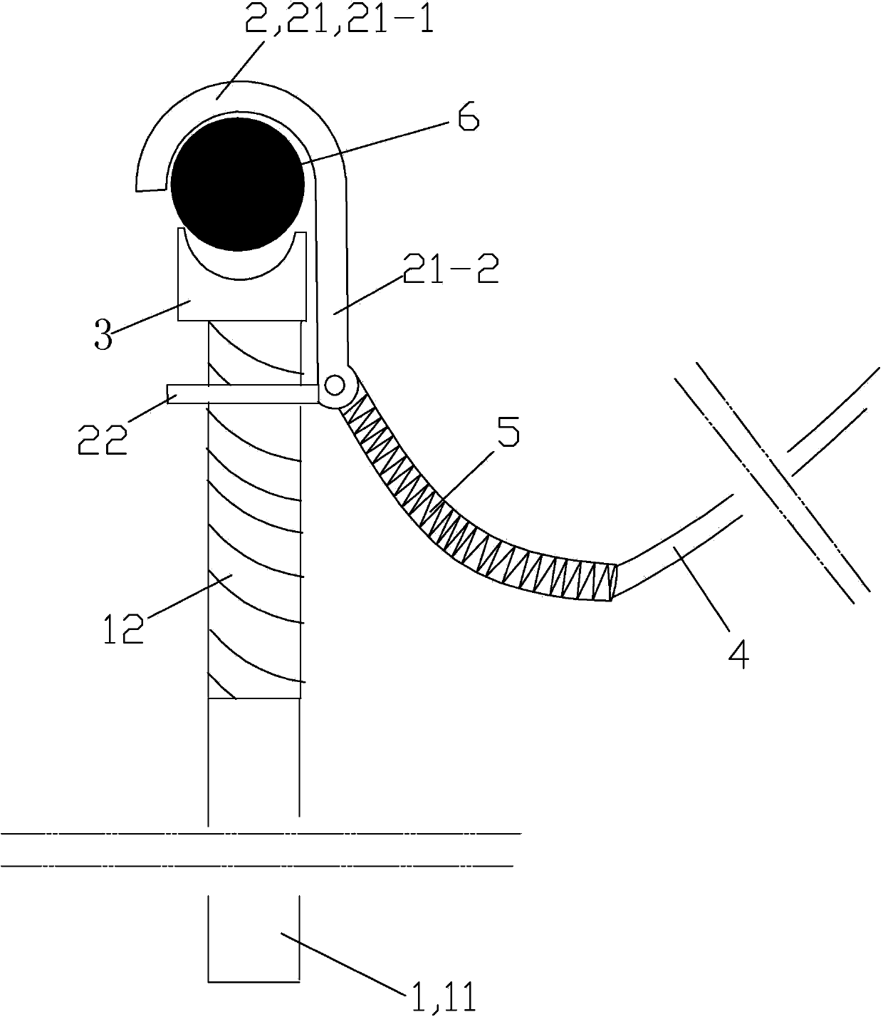
[0025] See figure 2 , The ground rod used for the power supply line of this embodiment is mainly composed of an operating rod 1, a hook 2, a bite plate 3, a ground soft copper wire 4 and a protection spring 5.
[0026] The operating rod 1 is fixedly connected with an insulating rod 11 located at the bottom and a screw rod 12 located at the top.
[0027] The hitch 2 is composed of a hitch plate 21 and an operating rod connecting plate 22 integrally connected. The hitch plate 21 is set vertically; the material of the hitch part 2 is a conductor. The hook plate 21 of the hook 2 is composed of an integrally connected arc portion 21-1 arranged on the upper part and a straight plate part 21-2 arranged on the lower part. The lower end of the straight plate portion 21-2 of the hitch plate 21 is provided with bolt holes that penetrate forward and backward; the operating rod connecting plate 22 is a plate body part that is arranged horizontally; The hitch plate 21 is integrally conn...
PUM
 Abstract
Description
Claims
Application Information