
Mechanism for detecting poor buckling of chain
A detection mechanism and chain technology, applied in the direction of measuring devices, instruments, etc., can solve problems such as the influence of small buckling detection, and achieve the effect of reducing resistance and damping, ensuring accuracy, and eliminating transverse shear force.
- Summary
- Abstract
- Description
- Claims
- Application Information
AI Technical Summary
Problems solved by technology
Method used
Image

Examples
Embodiment 1
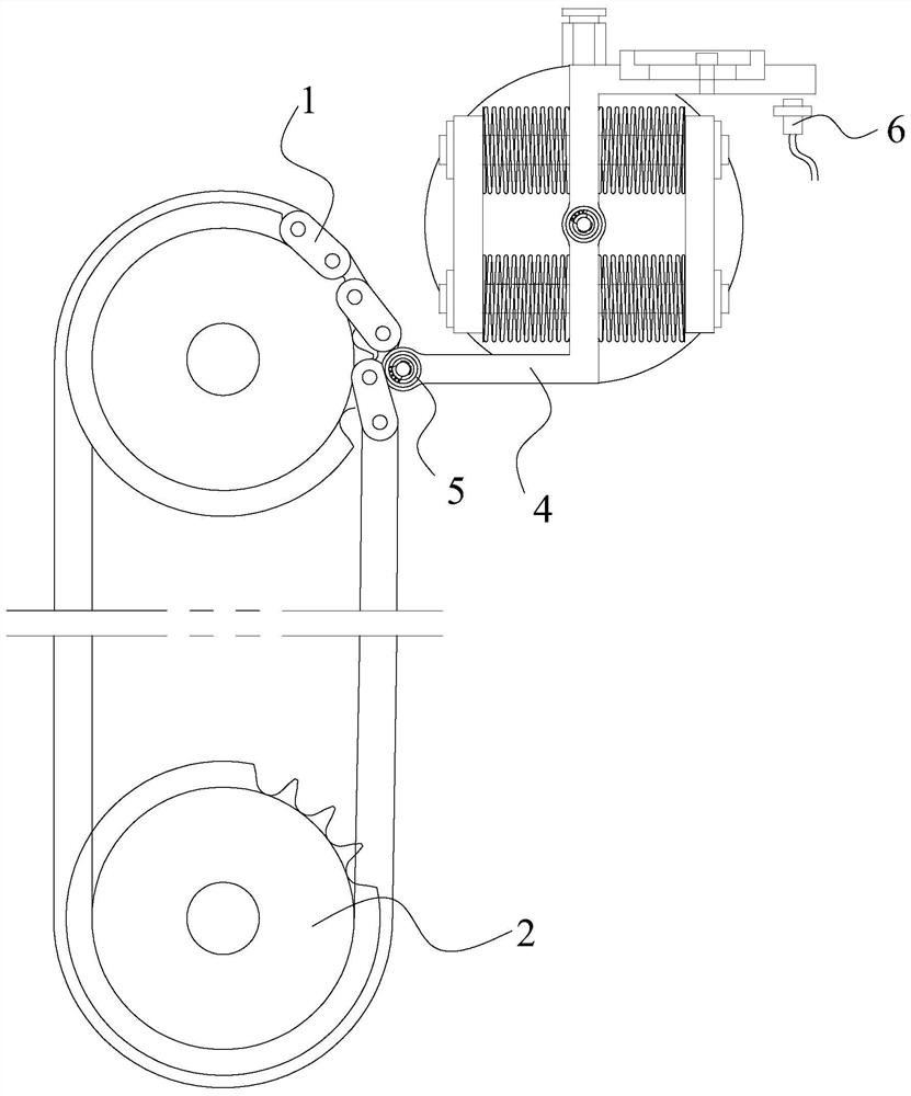
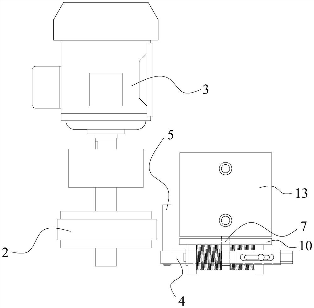
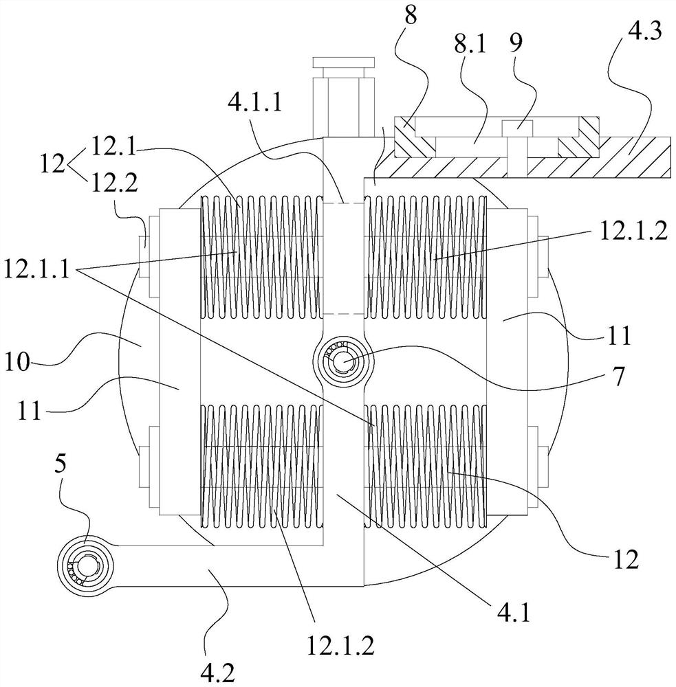
[0030] like figure 1 , 2 As shown in , 3, the present invention provides a detection mechanism for poor chain buckling, including a sprocket assembly 2 for installing the chain 1 to be detected and a drive motor 3 capable of driving the sprocket assembly 2 to rotate, specifically, the sprocket assembly 2 Including the driving wheel 2.1 and the driven wheel 2.2, the output shaft of the driving motor 3 is connected with the driving wheel 2.1 through the coupling, and the driving wheel 2.1 is assembled with the driven wheel 2.2 through the chain 1 to be detected to form a power and transmission system. , and before the test of chain 1, the transmission system should ensure that the chain 1 rotates at a constant speed.
[0031] In addition, as figure 1 As shown, a rotating bracket 4 rotatable along its own axis is also provided on one side of the sprocket assembly 2 near the driving wheel 2.1, and the direction of the rotation axis of the rotating bracket 4 is parallel to the di...
Embodiment 2
[0043] The structure of this embodiment is basically the same as that of the first embodiment. The only difference is that the structure of the sensor 6 is arranged at one end of the first connecting rod 4.1 near the second connecting rod 4.2. Specifically, the first connecting rod 4.1 is near the second connecting rod. One end of 4.2 is provided with a rectangular extension block 14, the extension block 14 is consistent with the extension direction of the positioning shaft 5, and the sensor 6 is arranged on the side of the extension block 14 close to the second link 4.2, such as Figure 4 shown.
Embodiment 3
[0045] The structure of this embodiment is basically the same as that of the first embodiment, the only difference is that the positioning shaft 5 is replaced with a gear structure, which can detect the poor buckling of the roller chain.
PUM
 Abstract
Description
Claims
Application Information