
Connector

Active Publication Date: 2019-08-15
YING HAO TECH CO LTD
View PDF15 Cites 1 Cited by
  • Summary
  • Abstract
  • Description
  • Claims
  • Application Information

AI Technical Summary

Benefits of technology

The patent aims to provide a connector that can be adapted to various devices by designing different terminals on a circuit board. This allows for slots in different devices to be easily accommodated. Additionally, the connector improves grounding, which enhances noise isolation, and uses ultraviolet glue to stabilize the terminals and prevent shaking. Overall, the patent proposes a versatile and efficient solution for connecting circuit boards.

Problems solved by technology

However, it causes trouble in production and costs a lot as well.

Method used


Image

  • Connector
  • Connector
  • Connector

Examples


first embodiment

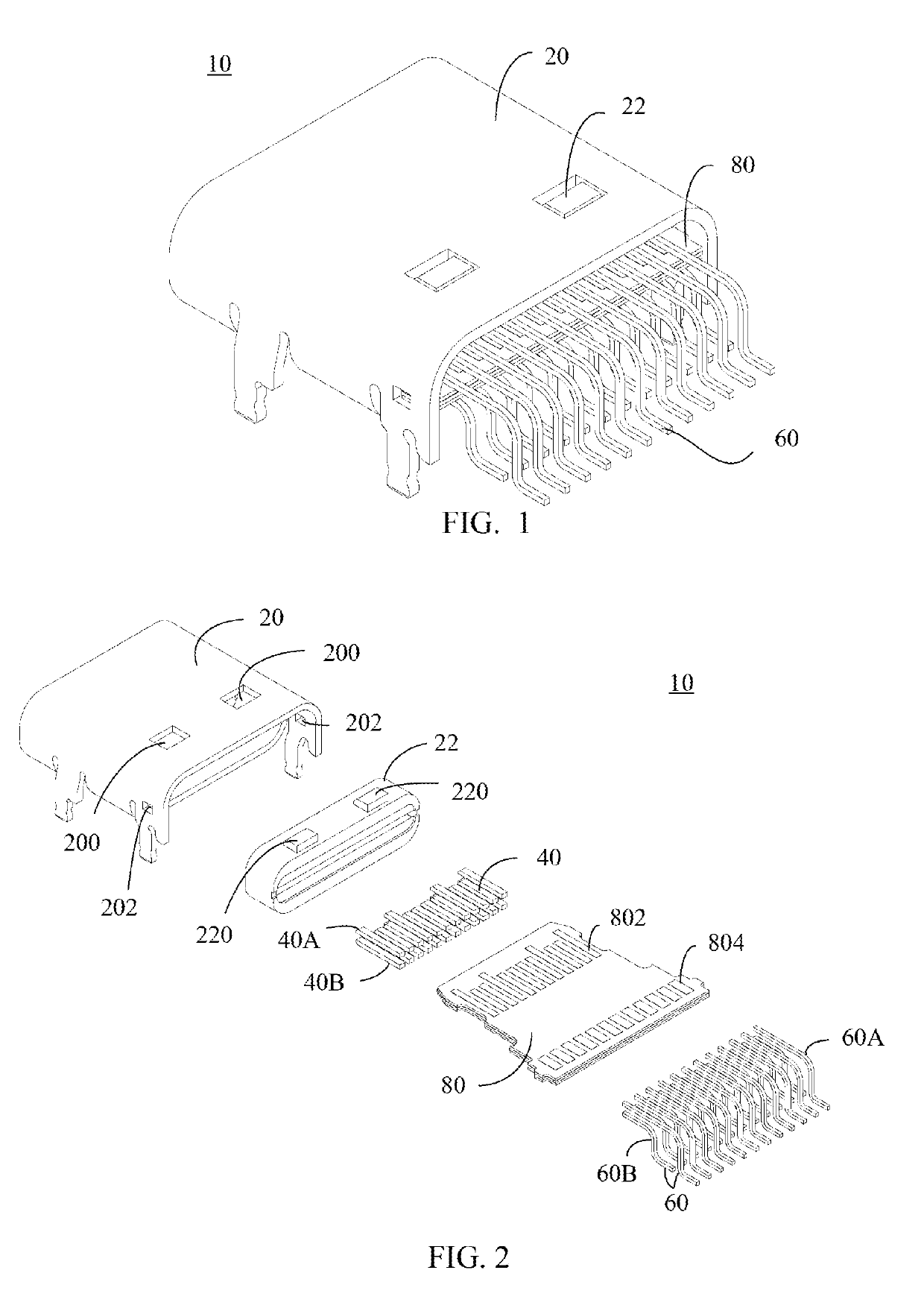
[0057]Please refer to FIG. 1 illustrating a diagram of a connector 10 according to the present disclosure. The connector 10 includes a shell 20, a cover 22, a connecting portion 60, and a circuit board 80. The shell 20 is configured to fix a slot of the connecting port of an external device. The connecting portion 60 is a connecting electronic device (not illustrated). The electronic device can be a storage device, a network device, a multimedia device, a communication terminal, a mechanical device, etc., and can be connected to an external device with the connector 10 of the present disclosure. Furthermore, the electronic device is connected to the connector 10 via the connecting portion 60 and is connected to the external device through the connector 10. In the present embodiment, the connecting portion 60 is a stripped terminal.

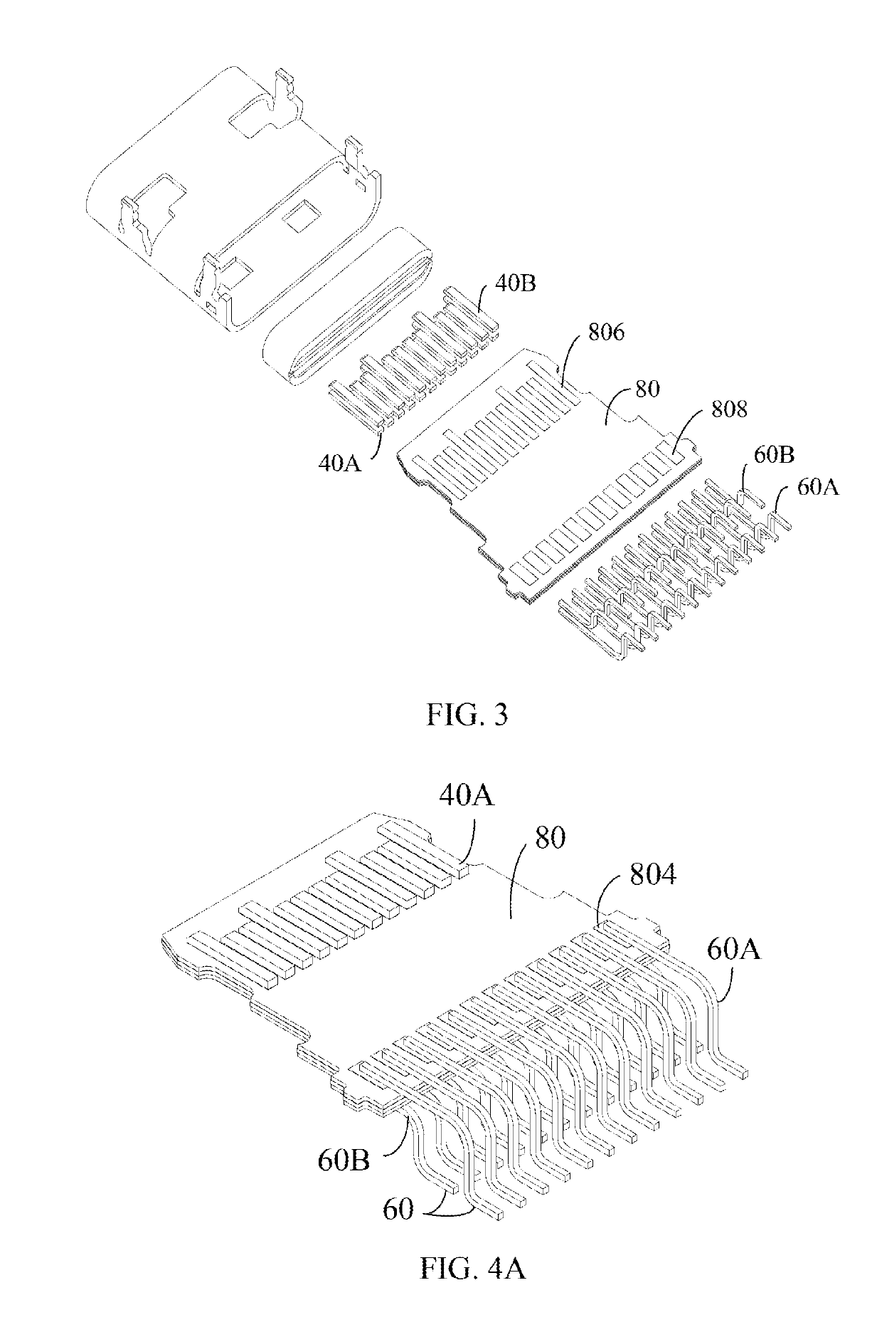
[0058]FIG. 2 is an exploded diagram of the first embodiment of the present disclosure. As illustrated in FIG. 2, the connector 10 includes a plurality of ...

fourth embodiment

[0074]FIG. 24A is an exploded diagram of the connector 10 according to the present disclosure. The structure of the connector 10 proposed by the present disclosure is similar to the connector 10 proposed by the present disclosure. The plurality of terminals 40 include a first terminal 40A and a second terminal 40B, and the first terminal 40A and the second terminal 40B are arranged on the upper and lower rows, respectively. The connecting portion 60 includes a first connecting portion 60A and a second connecting portion 60B, and the first connecting portion 60A and the second connecting portion 60B are arranged on the upper and lower rows, respectively. Since the upper and lower sides of the circuit board 80 are respectively provided with the second contact portion 804 and the fourth contact portion (on the side of the circuit board 80 opposite to the second contact portion 804), the width P1 of the second contact portion 804 and the width P1 of the fourth contact portion are only s...


PUM


Abstract

A connector includes a shell configured to protect the connector and to be plugged into a connecting port slot, a plurality of terminals electrically connected to the connecting port slot, a connecting portion connected to an electronic device, a circuit board, and a cover. The circuit board includes a first contact portion electrically connected to the plurality of terminals, and a second contact portion, electrically connected to the connecting portion. The cover is fixed to the shell. The shell is arranged between the circuit board and the shell to fix the circuit board in the shell.

Description

CROSS REFERENCE[0001]This application is claims the benefit and priority of Taiwanese Application No. 107202451, filed on Feb. 14, 2018. The entire disclosure of the above application is incorporated herein by reference.BACKGROUND1. Field of the Disclosure[0002]The present disclosure relates to a connector, and more particularly, to a connector with low production cost.2. Description of the Related Art[0003]Generally, a connector is designed in such a manner that the terminal is shaped as a bar and fixed to a circuit board correspondingly. However, there are a variety of electronic devices, and the specifications for connection between electronic devices are also different. Therefore, it is necessary to design a variety of terminal arrangements for a variety of specifications of connectors. It is also necessary to design a proper circuit board for a corresponding terminal. However, it causes trouble in production and costs a lot as well.SUMMARY[0004]In view of this, the purpose of t...

Claims


Application Information

Patent Timeline
IPC IPC(8): H01R13/6585H01R13/66H01R24/60
CPCH01R13/6585H01R13/665H01R24/60H01R43/24
Inventor CHEN, CHIH-JUNG
Owner YING HAO TECH CO LTD
Learn More