Low-power-consumption logic circuit

A low-power logic and logic circuit technology, applied in the field of logic circuits, can solve the problems of high dynamic current consumption, frequent system charging, and frequent battery replacement, etc., to achieve the effect of low power consumption

Inactive Publication Date: 2015-02-25
WUXI ZGMICRO ELECTRONICS CO LTD
View PDF6 Cites 1 Cited by
  • Summary
  • Abstract
  • Description
  • Claims
  • Application Information

AI Technical Summary

Problems solved by technology

[0005] The embodiment of the present invention provides a low-power logic circuit, which can solve the problem that the existing logic circuit consumes a large amount o

Method used


Image

  • Low-power-consumption logic circuit
  • Low-power-consumption logic circuit
  • Low-power-consumption logic circuit

Examples


Embodiment Construction

[0023] In order to make the purpose, technical solutions and advantages of the embodiments of the present invention clearer, the technical solutions in the embodiments of the present invention will be clearly and completely described below in conjunction with the drawings in the embodiments of the present invention. Obviously, the described embodiments It is a part of embodiments of the present invention, but not all embodiments. Based on the embodiments of the present invention, all other embodiments obtained by persons of ordinary skill in the art without making creative efforts belong to the protection scope of the present invention.

[0024] In order to facilitate the understanding of the embodiments of the present invention, further explanations will be given below with specific embodiments in conjunction with the accompanying drawings, which are not intended to limit the embodiments of the present invention.

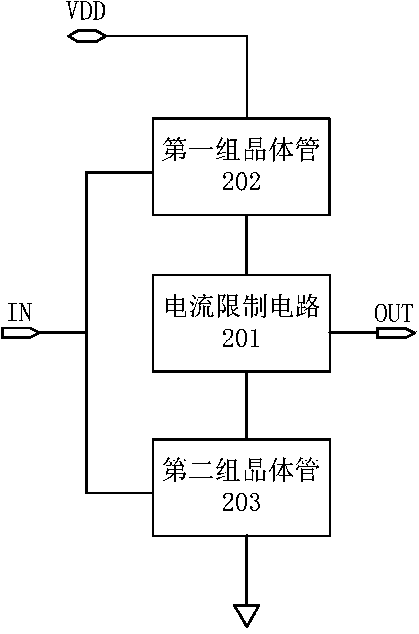
[0025] figure 2 A circuit schematic diagram of a low-power ...


PUM


Abstract

The embodiment of the invention relates to a low-power-consumption logic circuit. The low-power-consumption logic circuit comprises a current limiting circuit, a first transistor set and a second transistor set. The current limiting circuit is connected to an output end. The source electrode of the first transistor set is connected to a power supply end, the grid electrode of the first transistor set is connected to an input end, and the drain electrode of the first transistor set is connected to the current limiting circuit. The source electrode of the second transistor set is connected to a grounding end, the grid electrode of the second transistor set is connected to the input end, and the drain electrode of the second transistor set is connected to the current limiting circuit. When the first transistor set is switched on, a first current flows through the current limiting circuit to the second transistor set and is limited by the current limiting circuit to have the current value no larger than a preset threshold value, or when the second transistor set is switched on, a second current flows through the current limiting circuit to the first transistor set and is limited by the current limiting circuit to have the current value no larger than a preset threshold value. Thus, the problem that because an existing logic circuit consumes a large dynamic current when signals of the input end change, a system needs to be charged frequently or a battery of the system needs to be replaced frequently is can be solved.

Description

technical field [0001] The invention relates to the field of logic circuits, in particular to a logic circuit with low power consumption. Background technique [0002] With the development of the Internet of Things technology, people gradually have a demand for battery-powered systems that do not need to be charged for a long time and do not need to be replaced frequently, which requires that the power consumption of the system is relatively low (for example, according to the standard of down to the microampere level). [0003] The digital circuit in the existing system consumes a large dynamic current power consumption when it is flipped, which leads to a relatively large average power consumption of the system. Such as figure 1 shown in the circuit diagram of the existing logic circuit, as figure 1 shown, including a PMOS transistor and an NMOS transistor. Wherein, the source of the PMOS transistor is connected to the power supply VDD, and the source of the NMOS transi...

Claims


Application Information

Patent Timeline
IPC IPC(8): H03K19/173
Inventor 王钊
Owner WUXI ZGMICRO ELECTRONICS CO LTD
Why Eureka
Try Eureka