Intelligent rapid cooling device

A fast-cooling and intelligent technology, applied in home appliances, applications, kitchen appliances, etc., can solve the problems of complex structure design, high production cost, and inability to use, and achieve the effect of low manufacturing cost, simple structure, and silent operation

Inactive Publication Date: 2015-03-04
SUZHOU DELUSEN AUTOMATION SYST
View PDF8 Cites 1 Cited by
  • Summary
  • Abstract
  • Description
  • Claims
  • Application Information

AI Technical Summary

Problems solved by technology

[0004] Looking at the patented technologies listed above and the existing products on the market, we can see that the existing technical products have complex structural designs, and for these products, the production cost is high, and the later maintenance will become more complicated and troublesome ; and these existing cooling products are larger in size and are mostly used for production. For ordinary u

Method used


Image

  • Intelligent rapid cooling device

Examples


Embodiment Construction

[0017] The specific implementation manners of the present invention will be further described in detail below in conjunction with the accompanying drawings.

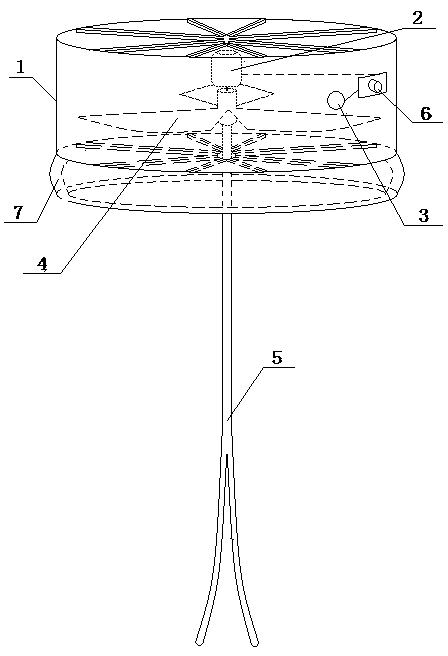
[0018] Such as figure 1 As shown, the present invention designs a kind of intelligent fast cooling device, comprises stirring rod 5, control switch 6, power base 1, and the motor 2 that is arranged in power base 1, power supply 3, fan blade 4; Wherein, power base The upper and lower surfaces of the seat 1 are hollow structures, the fan blade 4 is fixedly arranged on the rotating shaft of the motor 2, the fan blade 4 rotates with the rotation of the motor 2 rotating shaft, and the airflow direction of the fan blade 4 runs through the power base 1 On the upper and lower surfaces, the airflow direction is directed from the lower surface to the upper surface; the stirring rod 5 passes through the lower surface of the power base 1, and one end of the stirring rod 5 is connected with the end of the motor 2 rotating shaft, and...


PUM


Abstract

The invention relates to an intelligent rapid cooling device. A brand new structure is designed; according to the stirring principle, heat exchange processing is carried out; in addition, the acceleration air flowing principle is used in a combined manner to conduct cold and hot air convection; and rapid and convenient cooling operation on hot water is achieved. In addition, according to the technical scheme, the intelligent rapid cooling device is concise in structure, low in manufacturing cost, easy to achieve and convenient to maintain in the later period; and the service life of the intelligent rapid cooling device is greatly guaranteed.

Description

technical field [0001] The invention relates to an intelligent rapid cooling device. Background technique [0002] How to quickly cool a cup of hot water is a well-known method, which is nothing more than heat exchange or speeding up the flow speed of the liquid surface air. There are few such cooling products, such as patent application number: 201410044385.1, which discloses a stirring pot cooling device, including a stirring pot, one side of the stirring pot is provided with a feed port, and the lower layer of the stirring pot is provided with a cooling layer. A stirring mechanism is arranged in the stirring pot, and the stirring mechanism is connected with the driving and rotating mechanism through a connecting rod. A plurality of first grid blocking pieces and second grid blocking pieces are alternately arranged in parallel in the cooling layer. The first grid blocking pieces One end of the sheet is connected to the right side of the cooling layer, and the other side i...

Claims


Application Information

Patent Timeline
IPC IPC(8): A47J43/04
Inventor 徐花肖亚韪张静雅
Owner SUZHOU DELUSEN AUTOMATION SYST
Why Eureka
Try Eureka