Electric soldering equipment based on automotive electronic components

A technology of electronic components and automobiles, which is applied in the field of electric soldering equipment processing, can solve the problems of reducing the use effect, not having an auxiliary heat dissipation structure, and electric soldering equipment does not have multiple limit structures, so as to shorten the time and improve the accuracy.

Active Publication Date: 2022-08-09
安徽电通成套电气有限公司
View PDF8 Cites 0 Cited by
  • Summary
  • Abstract
  • Description
  • Claims
  • Application Information

AI Technical Summary

Problems solved by technology

[0004] The existing electric soldering equipment based on automotive electronic components has certain disadvantages in the process of use. The traditional electric soldering equipment based on automotive electronic components does not have an auxiliary fixing structure. Repeated calibration operations with electronic components reduce the working efficiency of electric soldering equipment; at the same time, traditional electric soldering equipment based on automotive electronic components does not have multiple limit structures, which reduces the use effect of its repeated processing operations; secondly, traditional based on The electric soldering equipment of automotive electronic components does not have an auxiliary heat dissipation structure, which reduces its use effect on multi-layer circuit boards and brings certain adverse effects to users

Method used


Image

  • Electric soldering equipment based on automotive electronic components
  • Electric soldering equipment based on automotive electronic components
  • Electric soldering equipment based on automotive electronic components

Examples


Embodiment 1

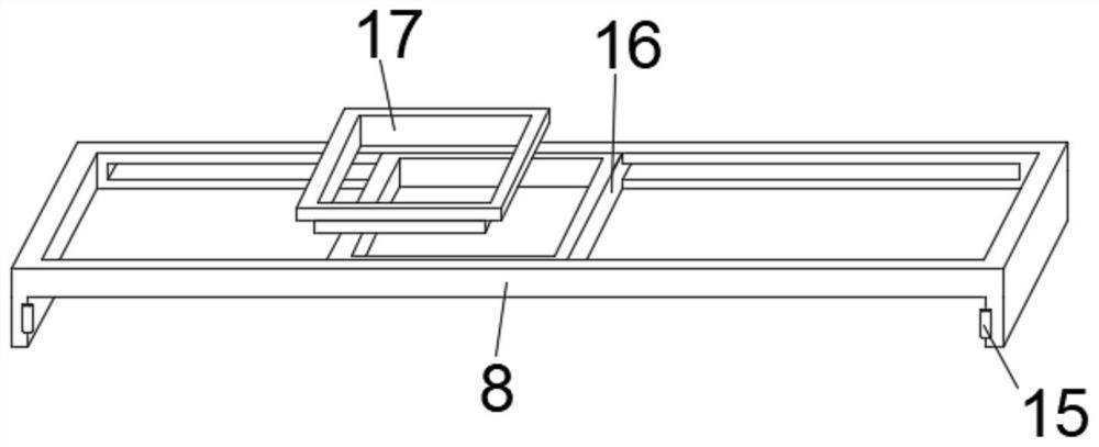
[0036] The middle of the sliding frame 16 is a rectangular hollow structure, the positioning carriage 8 and the sliding frame 16 are movably connected through the sliding slot, and the sliding frame 16 and the combination frame 17 are butted through the slot. When the electric soldering equipment is used, it can be used. According to the installation position of the electronic components, the sliding frame 16 is pushed on the inner side of the positioning carriage 8 by the chute, so that the installation positions of the sliding frame 16 and the electronic components are consistent, and the combination frame 17 of different sizes can be replaced according to the size of the electronic components. .

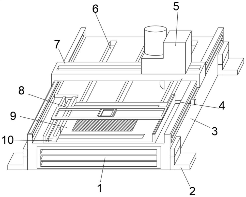
[0037] The upper end of the fixed base 3 is provided with three groups of push-pull grooves 6 side by side, and the bottom of the fixed card plate 9 is installed with two sets of limit card angles 12 that are docked with the push-pull grooves 6 . The setting can avoid the phenomen...

Embodiment 2

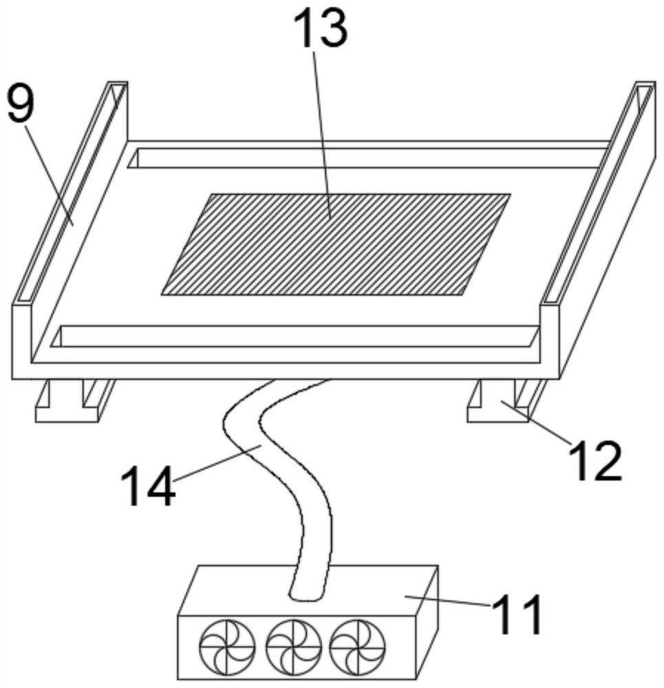
[0040] Both ends of the positioning carriage 8 are provided with sliding clamping wheels 15 , the inner side of the fixed clamping plate 9 is provided with a chute for docking the sliding clamping wheels 15 , and the upper outer surface of the fixed clamping plate 9 is movably installed with a fastening clamping plate 10 . When the electronic components on the circuit board are processed by electric soldering, the setting of the fastening card plate 10 can be used to fix the side of the circuit board to prevent the circuit board from loosening and falling off. At the same time, the setting of the sliding card wheel 15 can make the positioning The moving operation of the carriage 8 is smoother.

[0041] The fixed base 3 and the limit clamping rod 4 are butted by the chute, the outer surface of the limit clamping rod 4 is fixedly installed with a positioning socket 19, and one end of the limit clamping rod 4 is movably installed with a threaded sleeve rod 18, When the equipment ...

Embodiment 3

[0043] Two sets of lifting clips 2 are installed on both outer surfaces of the fixed base 3 , the fixed base 3 and the lifting clips 2 are connected and fixed by a fixing buckle 21 , and a telescopic sleeve 20 is movably installed on the inner side of the lifting clips 2 . The setting of the telescopic sleeve plate 20 can adjust the use length of the lifting clip 2, so as to play a balance adjustment effect on the placement of the electric soldering equipment.

[0044] The bottom of the fastening card 10 is installed with a sliding button 22 for docking the fixing card 9, the side of the fastening card 10 is fixedly installed with a rubber strip, and the sliding button 22 includes an upper clamping plate and a lower clamping plate. Bolts are installed between the bolts, and by rotating the bolts, the upper clamp plate and the lower clamp plate can be clamped and fixed, so that the moved clamping plate 10 plays a fixed role.

[0045] The front end of the fixed base 3 is fixedly...


PUM


Abstract

The electric soldering equipment based on automotive electronic components disclosed in the present invention comprises a fixed base, a tin-plated soldering gun and a fixed clamping plate. Above the board, a positioning carriage used to adjust the docking position of the electronic components is movably installed on the outer surface of the upper end of the fixed card board; the spliced ​​fixing structure between the sliding frame and the combination frame is used to replace the corresponding size combination on the sliding frame. When the electronic components are installed, the electronic components are put into the combination box. When the electronic components are dropped, the electronic components are accurately installed on the circuit board. When the components are repeatedly processed, the time required for the butt installation of the electronic components can be effectively shortened, and the precision of the electric soldering operation can be improved.

Description

technical field [0001] The invention belongs to the technical field of electric soldering equipment processing, and more particularly relates to an electric soldering equipment based on automotive electronic components and a method for using the same. Background technique [0002] Tin coating has been widely used in the electronics industry as a protective and solderable coating for electronic components, wires, printed circuit boards and integrated circuit blocks due to its excellent corrosion resistance and solderability. [0003] The patent document of the patent number CN201261813Y discloses a continuous electric welding tin equipment for strip steel, including an induction reflow device, a resistance reflow device, a reflow tower, and a steering roller for changing the direction of the strip, which are arranged in the running direction of the strip. The induction reflow device is arranged between the first conductive roller and the second conductive roller of the resist...

Claims


Application Information

Patent Timeline
Patent Type & Authority Patents(China)
IPC IPC(8): C25D7/00C25D17/00B23K3/08B23K101/36
CPCC25D17/00C25D7/00B23K3/085B23K3/087B23K3/08B23K2101/36
Inventor 徐如意
Owner 安徽电通成套电气有限公司
Why Eureka
Try Eureka