Injection die horizontal and vertical direction combination loose core mechanism

A vertical direction and injection mold technology, which is applied in the field of horizontal and vertical combined core-pulling mechanisms of injection molds, can solve the problems of plastic parts breaking and affecting product quality, etc.

Active Publication Date: 2015-03-11
ZHEJIANG KAIHUA MOLDS
View PDF6 Cites 7 Cited by
  • Summary
  • Abstract
  • Description
  • Claims
  • Application Information

AI Technical Summary

Problems solved by technology

[0002] If one side of the plastic part is formed with horizontal undercut and vertical undercut at the same time, the existing technology is to make the vertical undercut into an arc-shaped groove, set a slide block on the core, and be shaped on the slide block. Side core pulling and upper core pulling, so that when the mold is opened, the power drives the slider to be drawn out horizontally. If the inner wall of the undercut is made into a sharp angle or a right angle, it will not be able to come out, and if it is used forcibly, it may cause the plastic parts to be broken and affect the product quality

Method used


Image

  • Injection die horizontal and vertical direction combination loose core mechanism
  • Injection die horizontal and vertical direction combination loose core mechanism
  • Injection die horizontal and vertical direction combination loose core mechanism

Examples


Embodiment Construction

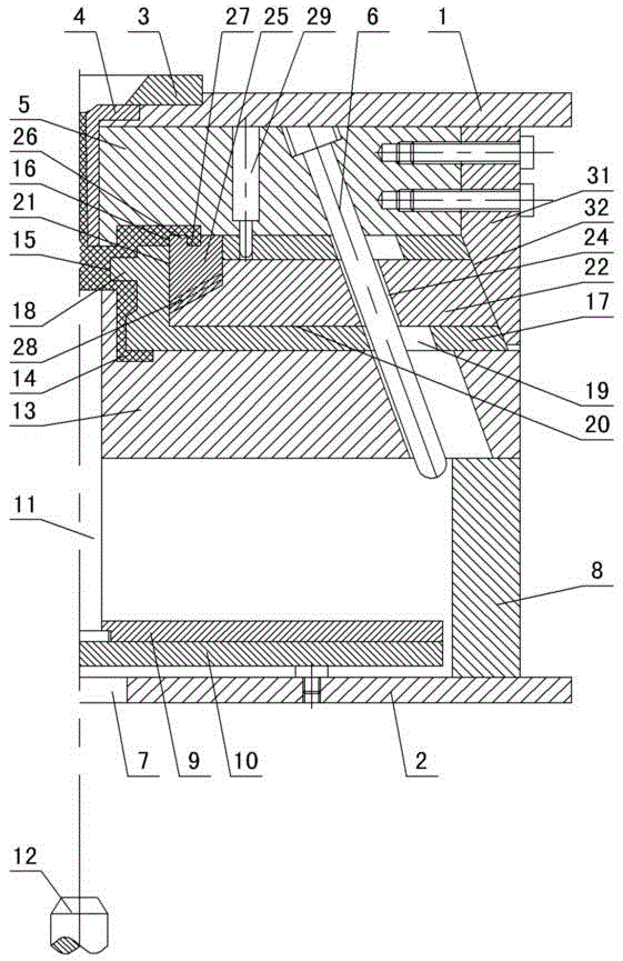
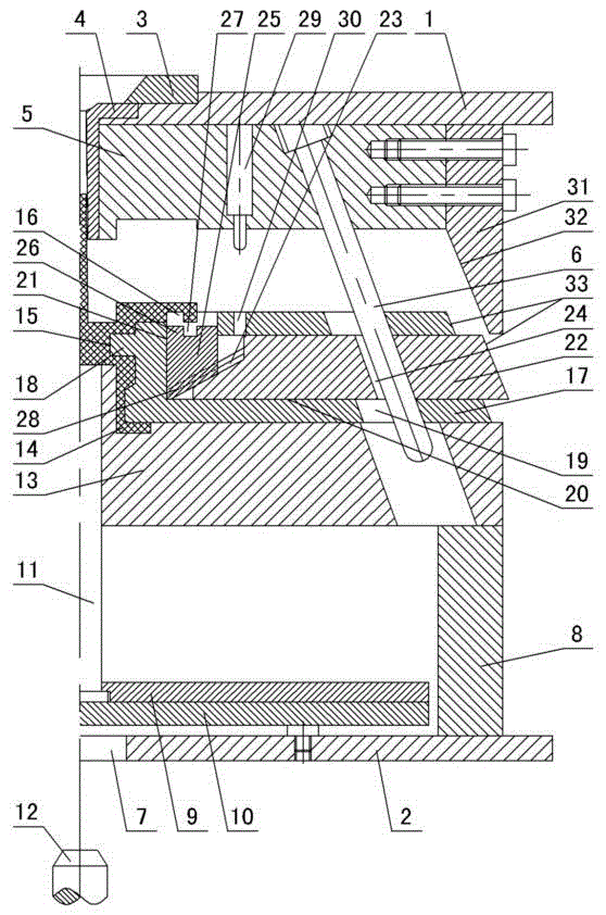
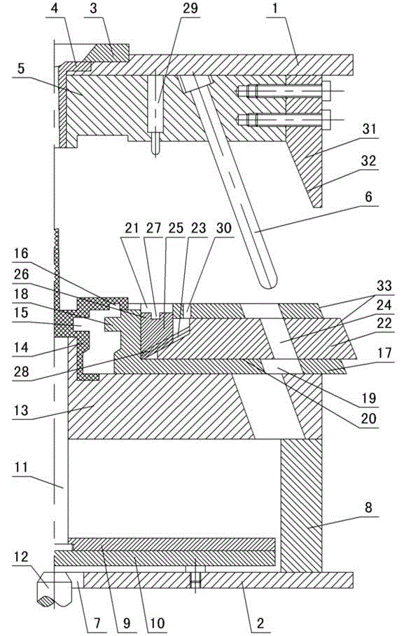
[0011] The invention relates to a combined core-pulling mechanism in the horizontal and vertical directions of an injection mold, such as figure 1 — Figure 4 As shown, it includes an upper doubler plate 1 and a lower doubler plate 2, a positioning ring 3 and a gate bushing 4 are set on the upper doubler plate, a cavity 5 is set under the upper doubler plate, an inclined guide column 6 is set in the cavity, and the lower doubler plate 2 is provided with a perforation 7, mold feet 8 are set on the lower doubler plate, an upper ejector plate 9 and a lower ejector plate 10 are arranged on the lower doubler plate between the mold feet, and ejector pins 11 are arranged between the upper and lower ejector plates. The rod 12 passes through the perforation and contacts the bottom of the lower ejector plate 10. A core 13 is set on the mold foot 8. There is an injection-molded plastic part 14 between the core and the cavity 5. One side of the plastic part is made with a horizontal side....


PUM


Abstract

An injection die horizontal and vertical direction combination loose core mechanism comprises an upper compound plate and a lower compound plate, a cavity is arranged below the upper compound plate, an inclined guide column is arranged in the cavity, the lower compound plate is provided with a through hole, the lower compound plate is provided with a die foot, the lower compound plate is provided with an upper thimble plate and a lower thimble plate, a thimble is arranged between the upper thimble plate and the lower thimble plate, an injection machine push rod traverses through the through hole and contacts with the lower thimble plate, the die foot is provided a core, a plastic member is arranged between the core and the cavity, one side of the plastic member is provided with a horizontal direction side undercut and a vertical direction side undercut, the core is provided with an outer slide block, one side of the outer slide block is provided with a side loose core, the side loose core cooperates with the plastic member horizontal direction undercut, a large inclined guide hole, a transverse loose core hole and a straight loose core hole are arranged in the outer slide block, an inner slide block is arranged in the transverse loose core hole, one side of the inner slide block is provided with an inclined slide slot, a small inclined guide hole is arranged in the inner slide block, the large and small inclined guide hole cooperate with the inclined guide column, a vertical loose core slide block is arranged in the straight loose core hole, the vertical loose core slide block is provided with an upper loose core and an upper groove, the upper loose core cooperates with the vertical direction side undercut, an inclined guide rail is arranged below the vertical loose core slide block, and the inclined guide rail cooperates with the inclined slide slot.

Description

technical field [0001] The invention relates to an injection mold, in particular to a combined core-pulling mechanism in the horizontal and vertical directions of the injection mold. Background technique [0002] If one side of the plastic part is formed with horizontal undercut and vertical undercut at the same time, the existing technology is to make the vertical undercut into an arc-shaped groove, set a slide block on the core, and be shaped on the slide block. Side core pulling and upper core pulling, so that when the mold is opened, the power drives the slider to be drawn out horizontally. If the inner wall of the direction undercut is made into a sharp angle or a right angle, it will not be able to come off, and if it is forced to come off, the plastic part may be broken, which will affect the product quality. Contents of the invention [0003] The purpose of the present invention is to overcome the shortcomings of the prior art, and to provide a kind of inclined gu...

Claims


Application Information

Patent Timeline
Patent Type & Authority Applications(China)
IPC IPC(8): B29C45/33B29C45/40
CPCB29C45/33B29C45/332B29C45/4005
Inventor 梁正华
Owner ZHEJIANG KAIHUA MOLDS
Why Eureka
Try Eureka