Elevator landing door device

A technology of door device and elevator floor, which is applied in the direction of elevators, transportation and packaging, and elevators in buildings. It can solve the problems of long movable hook ejector rod length, disappearance, and difficulty in opening doors, and achieves low processing accuracy requirements and reduced The effect of low design cost and material price

Active Publication Date: 2016-06-15
SHANGHAI MITSUBISHI ELEVATOR CO LTD
View PDF6 Cites 0 Cited by
  • Summary
  • Abstract
  • Description
  • Claims
  • Application Information

AI Technical Summary

Problems solved by technology

But this scheme has some obvious deficiencies: 1) the position of hall door movable locking hook relies on the restriction of strong magnetic element, and protection movable locking hook is sucked by strong magnetic element under normal circumstances, can not affect the normal operation of elevator, but in In the case of magnetic field interference, the magnetic force is likely to become weak or disappear, resulting in insufficient safety and reliability; 2) When the lock is unlocked for the first time, the original hall unlocking assembly pushes the protective movable lock hook up under the upward thrust, so that It is necessary to overcome the magnetic force that restricts the protection of the movable lock hook, and the door opening force is required to be large enough, so it is difficult to open the door; 3) The length of the movable hook ejector rod used for the second unlocking is long and easily deformed, resulting in the failure to open the door smoothly; 4) Hall door lock The hook and the protection hook cannot be in the locked state at the same time. When the hall door lock hook composed of the hall door movable lock hook and the hall door fixed lock hook fails, the protection movable lock hook and the protection fixed lock hook are in the unlocked state, and the floor cannot be locked. door; 5) Due to the use of magnetic elements and long ejector rods, the structure is complex and the cost is too high
Although this structure is relatively simple, there are still some disadvantages: 1) after skilled operation, it is easy to complete the unlocking process twice before and after in one operation, thus losing the function and purpose of secondary unlocking; The operation process is similar to the conventional landing door unlocking action, and there is still the risk that the human body may fall into the hoistway due to a high center of gravity; 3) The hall door lock hook composed of the main door hook and the main hook and the protection guard composed of the auxiliary door hook and the auxiliary hook The lock hook cannot be in the locked state at the same time. When the hall door lock hook fails, the protection lock hook is in the default unlocked state. Only the triangular key can be used to open the triangular lock of the landing door. The rotation of the triangular lock drives the pick to push the vertical push rod upward. Only when the auxiliary door hook rotates counterclockwise can it be locked with the auxiliary hook. Therefore, the protective lock hook cannot lock the landing door when no one is aware of the operation, and it is still impossible to avoid the accidental opening of the landing door under the action of external force.

Method used


Image

  • Elevator landing door device
  • Elevator landing door device
  • Elevator landing door device

Examples


Embodiment Construction

[0037] The present invention will be further described in detail below in conjunction with the accompanying drawings and specific embodiments.

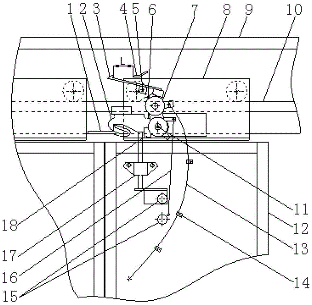
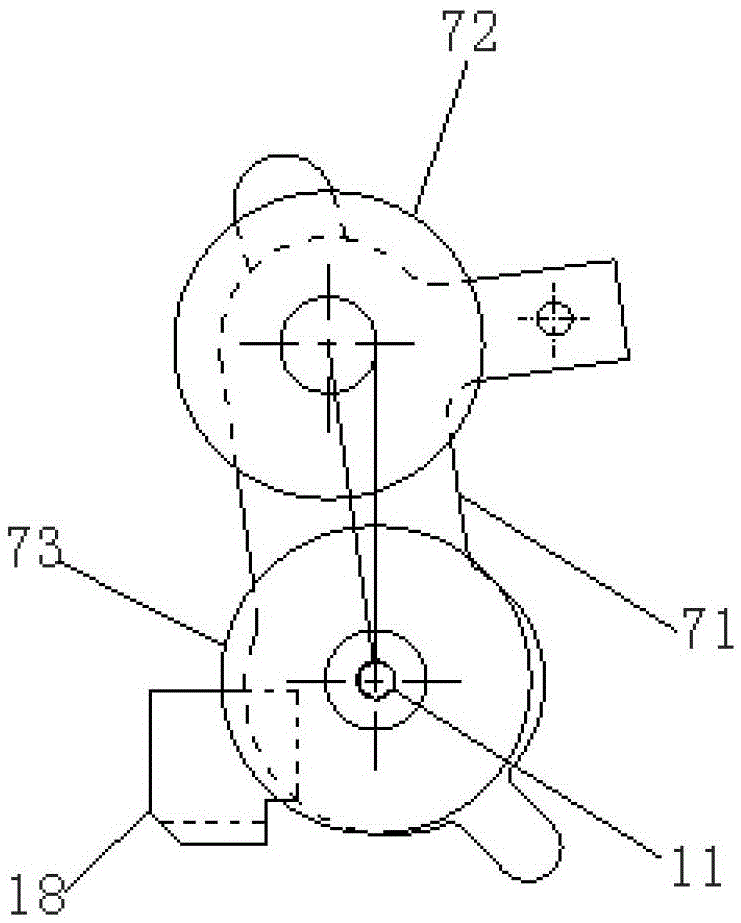
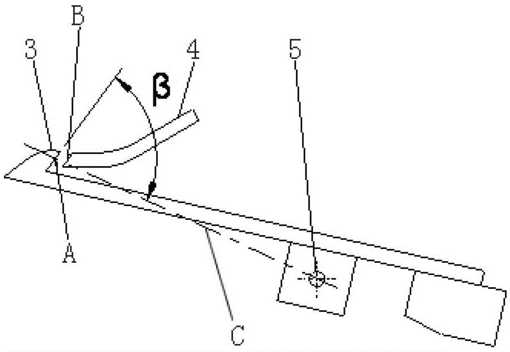
[0038] The elevator landing door device provided by the present invention includes a landing door device body 9, a door hanging plate 8, a door guide rail 10, a landing door 12, a first fixed hook 1, a first movable hook 2, a first unlocking unit, and a second fixed hook 4. The second movable hook 3, the second unlocking unit 7 and the manual operating member 13, wherein the first fixed hook 1 and the second fixed hook 4 are both fixedly installed on the landing door device body 9, and the second fixed hook 4 is located at Above the first fixed hook 1; the first movable hook 2 is installed on the door hanging plate 8 through a first fixed shaft 11 and can rotate around the fixed shaft 11; the second movable hook 3 is installed on the door through a second fixed shaft 5 on the hanging plate 8 and can rotate around the fixed shaft 5; th...


PUM


Abstract

The invention discloses an elevator landing door device. The elevator landing door device comprises a landing door device body, a door hanging plate, a door guide rail, a landing door, two fixed hooks, two flexible hooks, two unlocking units and a manual operating part; the first fixed hook and the second fixed hook are fixed on the landing door device body; the second fixed hook is arranged above the first fixed hook; the first flexible hook is arranged on the door hanging plate through a first fixed shaft and can rotate around the first fixed shaft; the first flexible hook is driven by the first unlocking unit to rotate to enable the first flexible hook to be separated from the first fixed hook; the second flexible hook is arranged on the door hanging plate through a second fixed shaft and can rotate around the second fixed shaft; the second flexible hook is driven by the second unlocking unit to rotate to enable the second flexible hook to be separated from the second fixed hook; the first flexible hook rotates in the opposite direction when the second flexible hook rotates; one end of the manual operating part is connected with the second unlocking unit; the other end of the manual operating part is located at the position of the landing door. According to the elevator landing door device, the risk of the accidental opening of the landing door due to the fact that one of locking mechanisms fails can be avoided due to the two locking mechanisms and the shaft falling is prevented through secondary unlocking.

Description

technical field [0001] The invention relates to an elevator device, in particular to an elevator landing door device that prevents users or maintenance personnel from falling down the hoistway due to the opening of the landing door. Background technique [0002] As the level of social urbanization is getting higher and higher, and the process of urbanization is getting faster and faster, more and more high-rise buildings are rising. Elevators, as an indispensable modern transportation tool, are inseparable from people's life and work. However, as the number of elevators in use continues to increase, safety accidents related to elevators also occur from time to time, among which passengers, maintenance personnel or rescue personnel accidentally fall into the shaft from the landing door of the landing and cause casualties more frequently occur. [0003] At present, commonly used elevator landing doors generally only have a pair of lock hooks, and mainly rely on external force...

Claims


Application Information

Patent Timeline
Patent Type & Authority Patents(China)
IPC IPC(8): B66B13/02B66B5/02B66B13/30
CPCB66B5/02B66B13/02B66B13/30
Inventor 金长明童正国
Owner SHANGHAI MITSUBISHI ELEVATOR CO LTD
Why Eureka
Try Eureka