Anti-vibration butterfly valve

An anti-vibration, butterfly valve technology, applied in the direction of lift valve, valve details, valve device, etc., can solve problems such as vibration

Active Publication Date: 2019-11-08
OUGUAN VALVE TECH
View PDF5 Cites 6 Cited by
  • Summary
  • Abstract
  • Description
  • Claims
  • Application Information

AI Technical Summary

Problems solved by technology

[0002] Butterfly valve, also known as flap valve, is a regulating valve with simple structure. Butterfly valve is suitable for producing furnace, coal gas, natural gas, liquefied petroleum gas, city gas, hot and cold air, chemical smelting and power generation environmental protection, building water supply and drainage and other engineering systems It is used to adjust and cut off the flow of medium on pipelines that transport various corrosive and non-corrosive fluid media. However, when the butterfly valve in the prior art is in use, when the fluid pressure difference in the flow channel of the valve body fluctuates greatly, The valve core will vibrate due to continuous impact, and even automatically fall to close the flow channel of the valve body; therefore, we propose an anti-vibration butterfly valve to solve the above problems

Method used


Image

  • Anti-vibration butterfly valve
  • Anti-vibration butterfly valve
  • Anti-vibration butterfly valve

Examples


specific Embodiment approach 1

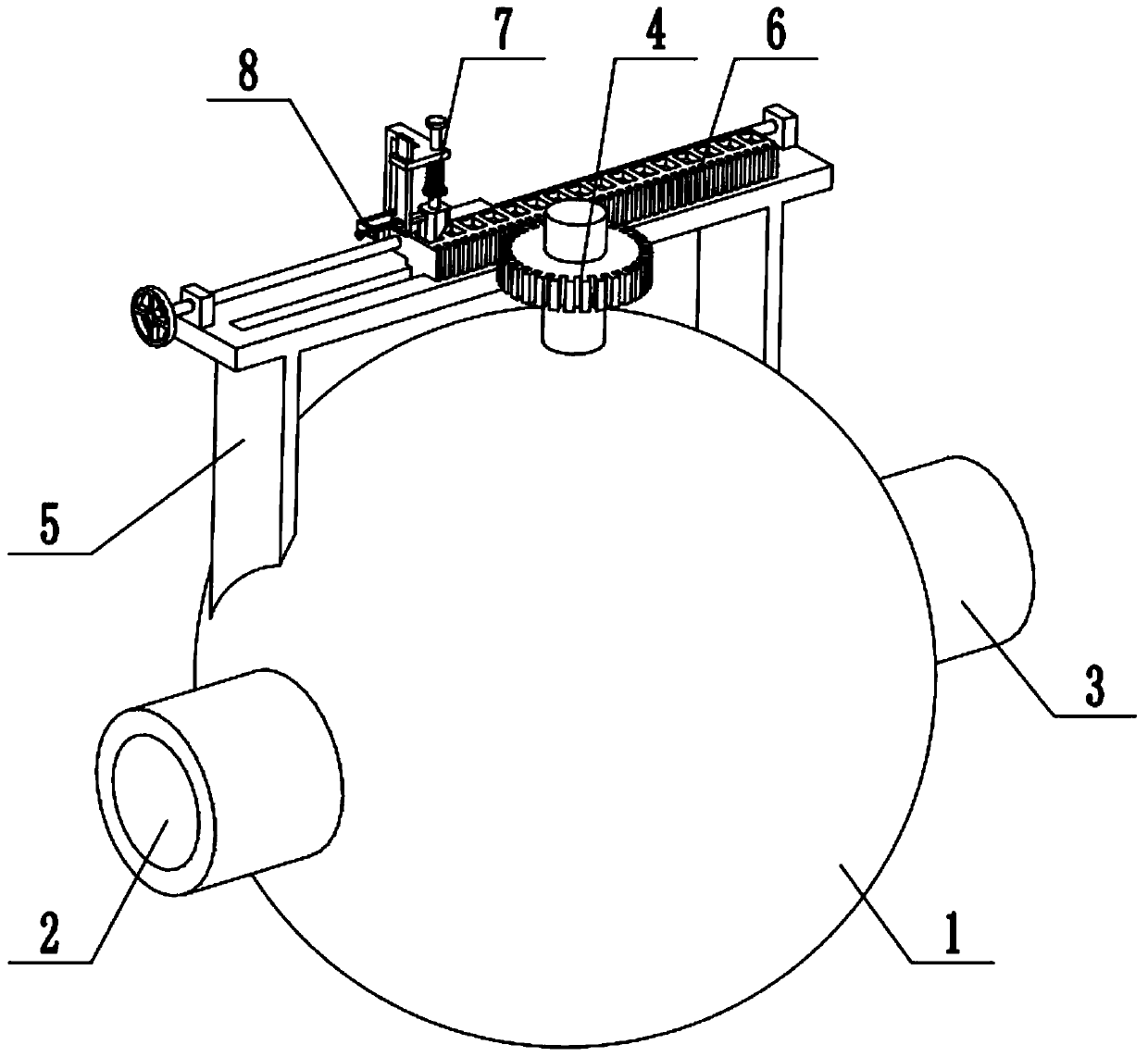
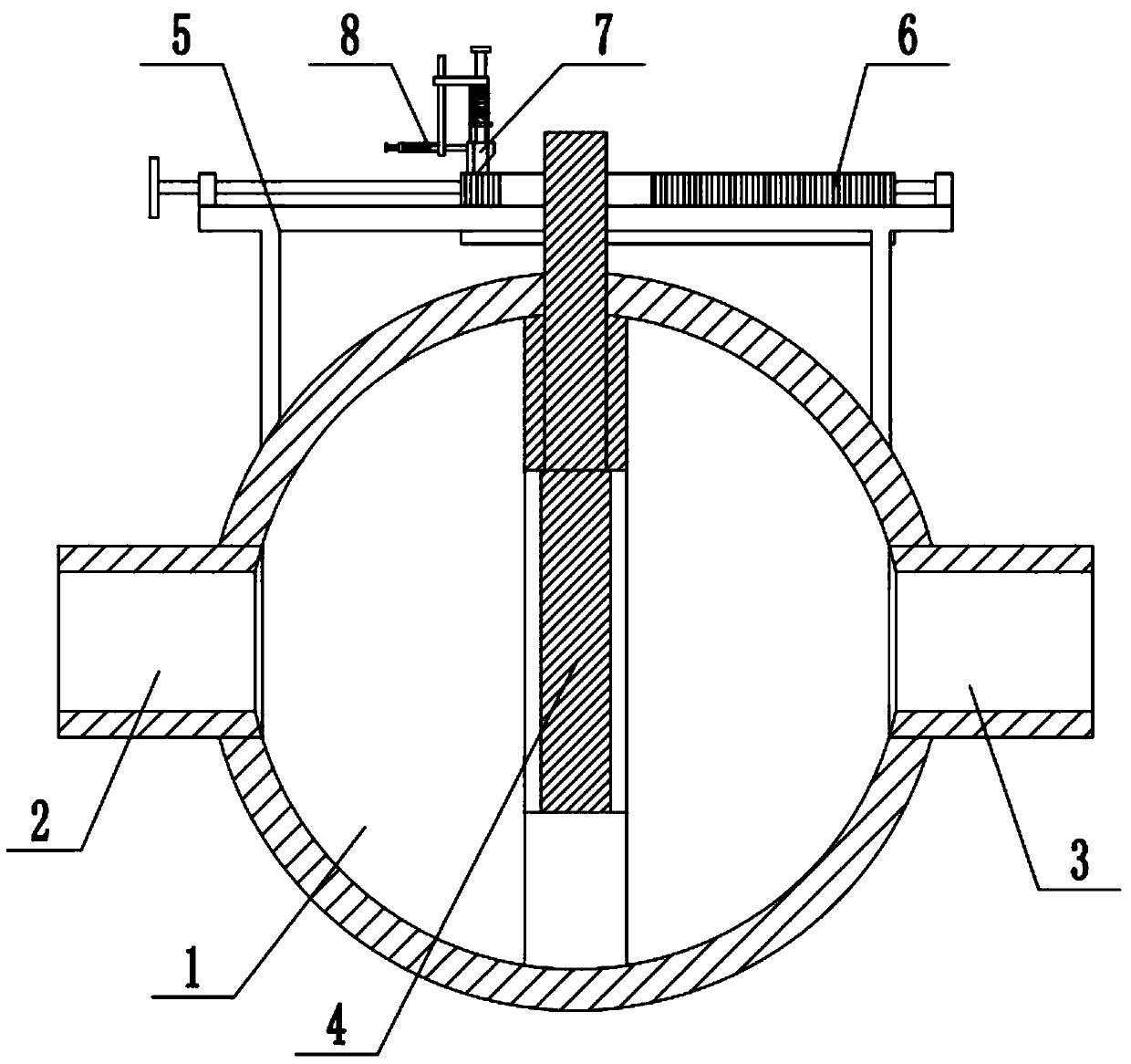
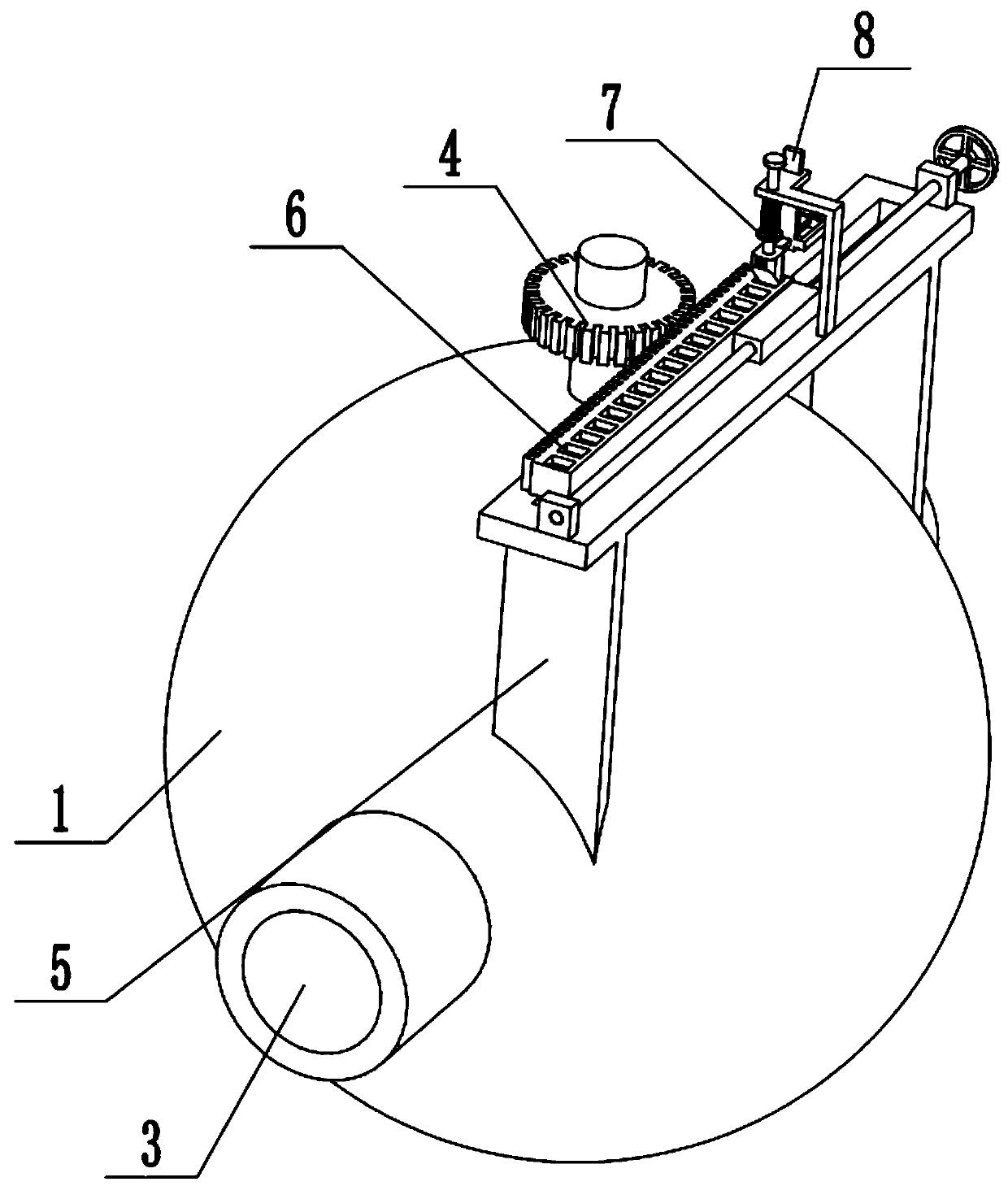
[0028] Combine below Figure 1-11 Describe this embodiment, an anti-vibration butterfly valve, including a valve body 1, a water inlet pipe 2, a drain pipe 3, a butterfly plate assembly 4, a frame body 5, a rack 6, a clip 7 and a limit mechanism 8, the valve The left end of the body 1 is fixedly connected to and connected to the water inlet pipe 2, the right end of the valve body 1 is fixedly connected to and connected to the drain pipe 3, the butterfly plate assembly 4 is arranged in the middle of the valve body 1, the frame body 5 is fixedly connected to the upper end of the valve body 1, and the teeth The bar 6 is arranged on the frame body 5, the butterfly plate assembly 4 is connected to the rack body 6 in transmission, the clip 7 is fixedly connected to the frame body 5, the clip 7 is blocked on the rack body 6, and the limit mechanism 8 is slidably connected to the frame body 5. On the clip 7 , the limit mechanism 8 is connected with the clip 7 . When the present inven...

specific Embodiment approach 2

[0030] Combine below Figure 1-11 To illustrate this embodiment, the middle part of the inner side of the valve body 1 is fixedly connected to the butterfly plate seat 1-1, the center of the butterfly plate seat 1-1 is provided with a liquid hole 1-2, and the shaft slide groove 1-3 is provided through the valve body. The upper end of the body 1 and the upper end of the disc seat 1-1, the rotating shaft chute 1-3 communicate with the liquid hole 1-2.

specific Embodiment approach 3

[0032] Combine below Figure 1-11 To illustrate this embodiment, the butterfly plate assembly 4 includes a butterfly plate 4-1, a rotating shaft 4-2 and a gear 4-3; the upper end of the butterfly plate 4-1 is fixedly connected to the rotating shaft 4-2, and the rotating shaft 4-2 is fixedly connected to the The gear 4-3 and the butterfly plate 4-1 are located in the liquid hole 1-2, the circular end surface of the butterfly plate 4-1 is provided with a sealing rubber pad, and the rotating shaft 4-2 is sealed and slidably connected to the rotating shaft chute 1-3 Inside, the gear 4-3 is connected with the gear rack 6 in meshing transmission. The butterfly plate 4-1 is located in the liquid hole 1-2, and the liquid hole 1-2 is blocked to be in a closed state. When the rack 6 moves left and right, it drives the gear 4-3 to rotate, and the gear 4-3 drives the rotating shaft 4-2 to rotate. , the rotating shaft 4-2 drives the butterfly plate 4-1 to rotate, thereby realizing the ope...


PUM


Abstract

The invention discloses an anti-vibration butterfly valve, and relates to the technical field of valve equipment. The anti-vibration butterfly valve comprises a valve body, a water inlet pipe, a drainage pipe, a butterfly plate component, a frame body, a rack, a clamping part and a limiting mechanism. The anti-vibration butterfly valve has the beneficial technical effects that the situation that the valve is opened or closed by mistake due to the fact that the valve body is vibrated because of being impacted can be avoided, when the anti-vibration butterfly valve is in an opened state, and aclamping block on the clamping part can keep the anti-vibration butterfly valve in the opened state; when the anti-vibration butterfly valve is in a closed state, the anti-vibration butterfly valve can be kept in the closed state by adjusting the direction of the clamping block on the clamping part, the left end of the valve body is fixedly connected with and communicates with the water inlet pipe, the right end of the valve body is fixedly connected with and communicates with the drainage pipe, the butterfly plate component is arranged in the middle of the valve body, the frame body is fixedly connected to the upper end of the valve body, the rack is arranged on the frame body, and the butterfly plate component is in transmission connection with the rack. The clamping part is fixedly connected to the frame body, the clamping part is clamped on the rack, the limiting mechanism is connected on the clamping part in a sliding fit manner, and the limiting mechanism is connected with the clamping part.

Description

technical field [0001] The invention relates to the technical field of valve equipment, in particular to an anti-vibration butterfly valve. Background technique [0002] Butterfly valve, also known as flap valve, is a regulating valve with simple structure. Butterfly valve is suitable for producing furnace, coal gas, natural gas, liquefied petroleum gas, city gas, hot and cold air, chemical smelting and power generation environmental protection, building water supply and drainage and other engineering systems It is used to adjust and cut off the flow of medium on pipelines that transport various corrosive and non-corrosive fluid media. However, when the butterfly valve in the prior art is in use, when the fluid pressure difference in the flow channel of the valve body fluctuates greatly, The spool will vibrate when subjected to continuous impact, and even automatically fall to close the flow channel of the valve body; therefore, we propose an anti-vibration butterfly valve t...

Claims


Application Information

Patent Timeline
Patent Type & Authority Applications(China)
IPC IPC(8): F16K1/22F16K31/54F16K35/10
CPCF16K1/221F16K31/54F16K35/10
Inventor 许津元
Owner OUGUAN VALVE TECH
Why Eureka
Try Eureka