Measuring instrument line laser measuring head calibration system and method

A technology of laser measuring head and measuring instruments, which is applied in the direction of instruments, measuring devices, optical devices, etc., can solve the problems of contour error, measurement value cannot be realized, measurement value deviation of the object to be measured, etc., and achieve the effect of accurate contour data

Inactive Publication Date: 2015-03-18
HONG FU JIN PRECISION IND (SHENZHEN) CO LTD +1
View PDF0 Cites 12 Cited by
  • Summary
  • Abstract
  • Description
  • Claims
  • Application Information

AI Technical Summary

Problems solved by technology

[0002] At present, when the measuring instrument uses a line laser probe to measure the object to be measured, a line laser probe can only measure the profile data of one surface of the object to be measured. The measured value of the object to be measured (for example, the thickness of the object to be measured needs to be obtained) cannot be realized
When using two line laser probes to measure the two surfaces of the object to be measured, due to the inconsistency of the installation angles of the two line laser probes and the inconsistency of the specifications of the two line laser probes, it may cause differences in the measured contours of the object to be measured. There is an error between them, which makes the measured value of the object to be measured deviate

Method used


Image

  • Measuring instrument line laser measuring head calibration system and method
  • Measuring instrument line laser measuring head calibration system and method
  • Measuring instrument line laser measuring head calibration system and method

Examples


Embodiment Construction

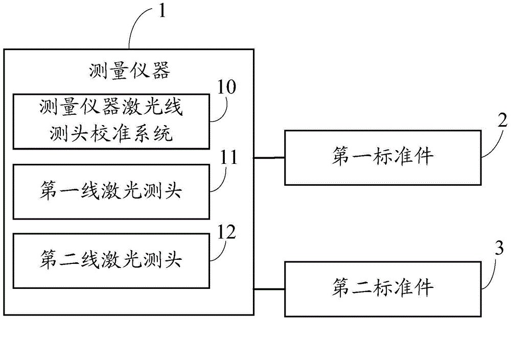
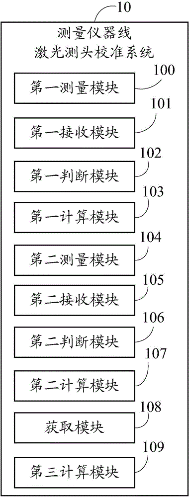
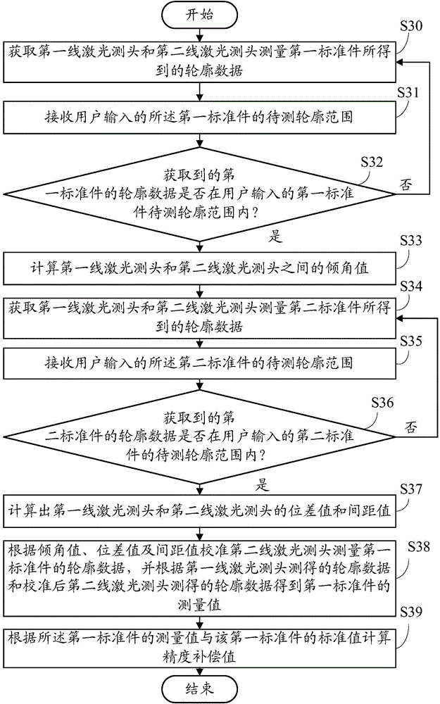
[0018] Such as figure 1 Shown is an operating environment diagram of a preferred embodiment of the measuring instrument line laser probe calibration system of the present invention. The measuring instrument line laser probe calibration system 10 runs on the measuring instrument 1 , and the measuring instrument 1 is equipped with two line laser probes, namely a first line laser probe 11 and a second line laser probe 12 . The first-line laser measuring head 11 and the second-line laser measuring head 12 are located on both sides of the object to be measured, and the lasers emitted by the first-line laser measuring head 11 and the second-line laser measuring head 12 intersect on the object to be measured. The measuring instrument line laser probe calibration system 10 uses the first standard part 2 and the second standard part 3 to calibrate and compensate the first line laser probe 11 and the second line laser probe 12, so that the first line laser probe 11 and the second line ...


PUM


Abstract

A measuring instrument line laser measuring head calibration system includes a first measuring module used for obtaining a first line laser measuring head and a second line laser measuring head to measure contour data of a first standard component; a first calculating module used for calculating a value of an angle of tilt between the first line laser measuring head and the second line laser measuring head; a second measuring module used for obtaining the first line laser measuring head and the second line laser measuring head to measure contour data of the second standard component; a second calculating module used for calculating values of potential difference and interval between the first line laser measuring head and the second line laser measuring head; an acquisition module used for calibrating, according to the value of the angel of tilt, the potential difference value and the interval value, the contour data of the first standard component measured by the second line laser measuring head to obtain a measured value of the first standard component; and a third calculating module used for calculating a precision compensation value according to the measured value and a standard value of the first standard component. The invention also provides a measuring instrument line laser measuring head calibration method. By use of the measuring instrument line laser measuring head calibration system and method provided by the invention, the two line laser measuring heads can be used to accurately measure an object to be measured.

Description

technical field [0001] The invention relates to a system and a method for calibrating a measuring instrument, in particular to a system and a method for calibrating a line laser measuring head of a measuring instrument. Background technique [0002] At present, when the measuring instrument uses a line laser probe to measure the object to be measured, a line laser probe can only measure the profile data of one surface of the object to be measured. The measured value of the object to be measured (for example, the thickness of the object to be measured needs to be obtained) cannot be realized. When using two line laser probes to measure the two surfaces of the object to be measured, due to the inconsistency of the installation angles of the two line laser probes and the inconsistency of the specifications of the two line laser probes, it may cause differences in the measured contours of the object to be measured. There is an error between them, which makes the measured value ...

Claims


Application Information

Patent Timeline
Patent Type & Authority Applications(China)
IPC IPC(8): G01B11/24
Inventor 张滋徐韦陈斌屈保锋
Owner HONG FU JIN PRECISION IND (SHENZHEN) CO LTD
Why Eureka
Try Eureka