Display equipment with camera

A display device and camera technology, applied in mechanical equipment, image communication, color TV parts, etc., can solve problems such as inconvenient use

Inactive Publication Date: 2015-03-18
HONG FU JIN PRECISION IND (SHENZHEN) CO LTD +1
View PDF5 Cites 5 Cited by
  • Summary
  • Abstract
  • Description
  • Claims
  • Application Information

AI Technical Summary

Problems solved by technology

[0002] Traditional display devices such as all-in-one machines or monitors generally include a display screen. Usually, in order to facilitate video communication, a camera is also installed on the upper part or other edge of the display screen; the display screen is generally rotatably installed on one foot. On the stand, the user can rotate the display screen relative to the tripod to adjust the display angle of the display screen during use, so that the user can watch the display screen from a comfortable angle, but when the display screen rotates, it will drive the camera to rotate together, thus changing the camera The angle of the captured image, at this time, it is necessary to adjust the angle of the camera to capture the image; this traditional display device will inevitably change the angle of the camera’s captured image when adjusting the display angle of the display screen, requiring the user to readjust the camera The angle at which the image is taken is inconvenient to use

Method used


Image

  • Display equipment with camera
  • Display equipment with camera
  • Display equipment with camera

Examples


Embodiment Construction

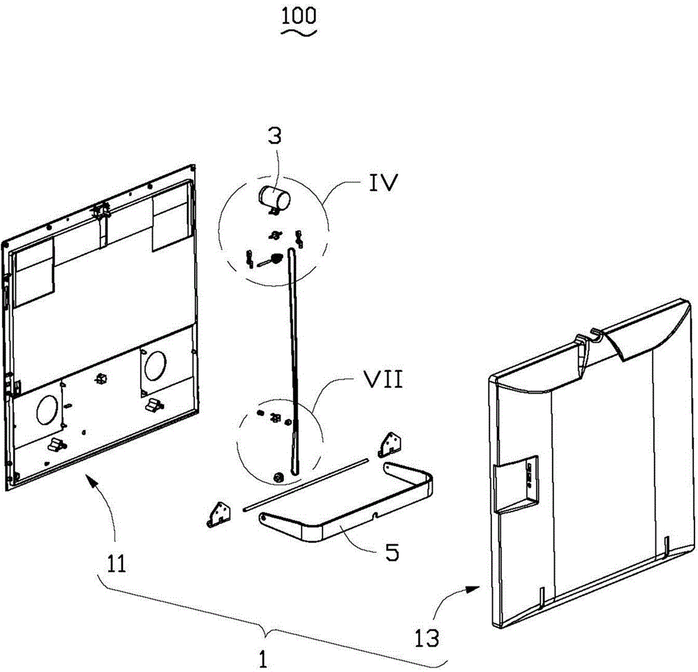
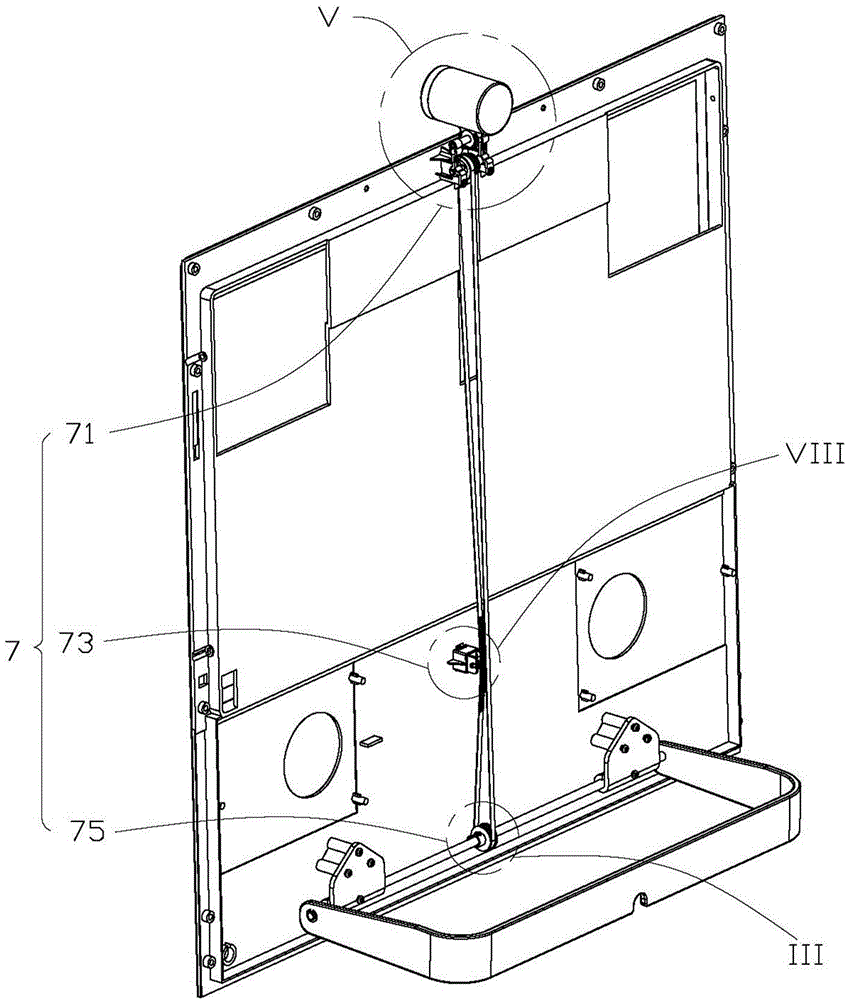
[0026] Please refer to figure 1 and figure 2 , a display device 100 that can synchronously adjust the camera provided by the present invention includes a housing 1 , a camera 3 , a tripod 5 , a synchronous transmission assembly 7 and a tensioning device 9 . The housing 1 includes a display screen 11 and a rear cover 13. The synchronous transmission assembly 7 is fixedly arranged on the rear surface of the display screen 11 opposite to the rear cover 13. When the display screen 11 and the rear cover 13 are fastened together, the synchronous transmission assembly 7 Stored in the housing 1; the bottom of the display screen 11 is rotatably mounted on the tripod 5, and the camera 3 is rotatably mounted on the top of the display screen 11.

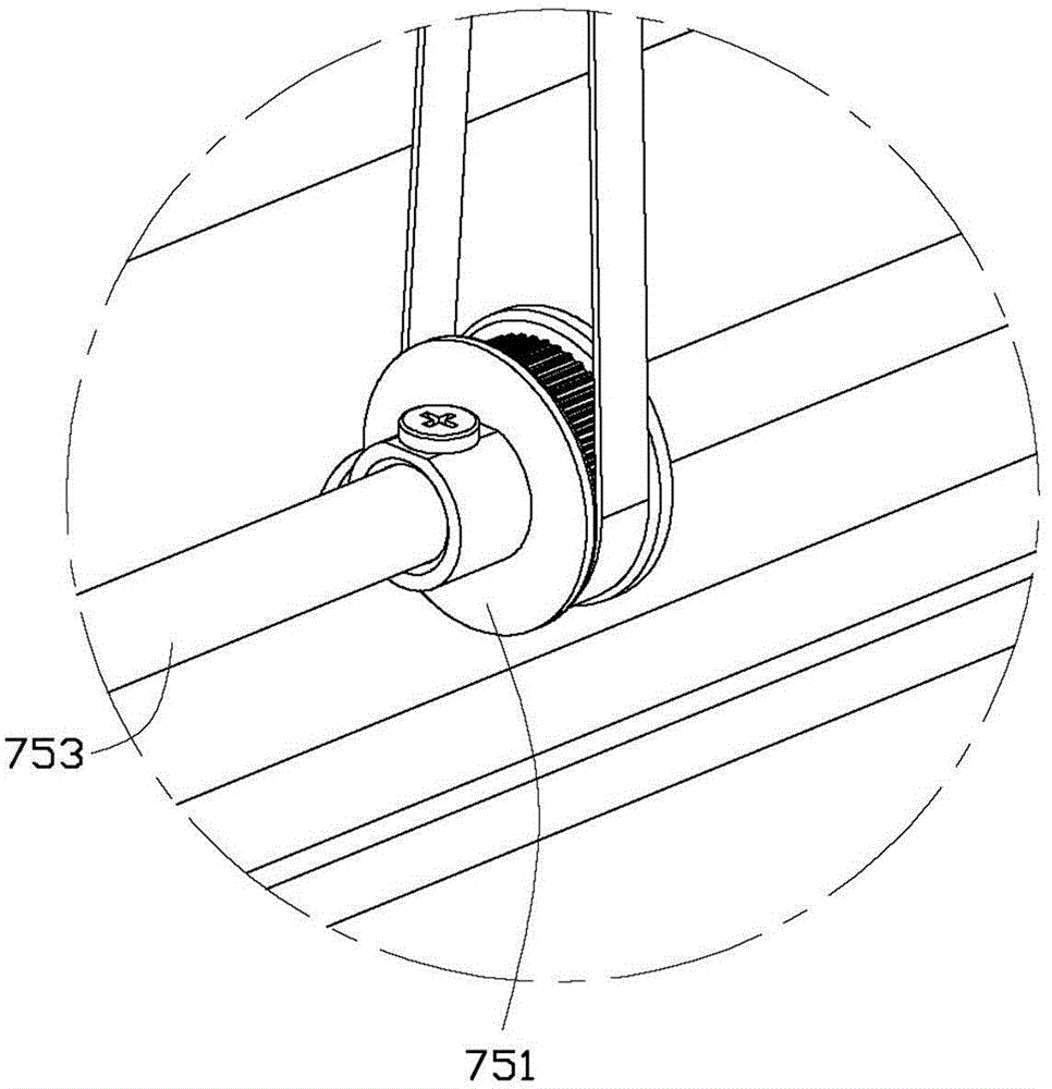
[0027] The synchronous transmission assembly 7 includes a camera rotation module 71 , a tripod rotation module 75 and a transmission device 73 . In this embodiment, the camera rotation module 71 is arranged on the top of the display screen 11...


PUM


Abstract

The invention provides display equipment with a camera, comprising a shell body, the camera and a foot bracket, wherein the camera is fixed on the shell body; the shell body is internally provided with a synchronous transmission component; the synchronous transmission component comprises a camera rotation module, a foot bracket rotation module and a transmission device; the camera rotation module is connected with the camera, and is capable of enabling the camera to rotate; the foot bracket rotation module is fixedly arranged on a display screen, and is capable of enabling the display screen to rotate relative to the foot bracket; the transmission device is connected between the camera rotation module and the foot bracket rotation module, and is used for realizing the linkage between the camera rotation module and the foot bracket rotation module; the foot bracket rotation module drives the camera rotation module to rotate through the transmission device when the shell body rotates relative to the foot bracket, so that an angle between the camera and the shell body is adjusted. According to the display equipment with the camera provided by the invention, a user can adjust the angle of the camera synchronously in the process of adjusting the display angle of the display screen, so that the user conveniently uses the display equipment with the camera.

Description

technical field [0001] The present invention relates to a display device, in particular to a display device with a camera. Background technique [0002] Traditional display devices such as all-in-one machines or monitors generally include a display screen. Usually, in order to facilitate video communication, a camera is also installed on the upper part or other edge of the display screen; the display screen is generally rotatably installed on one foot. On the stand, the user can rotate the display screen relative to the tripod to adjust the display angle of the display screen during use, so that the user can watch the display screen from a comfortable angle, but when the display screen rotates, it will drive the camera to rotate together, thus changing the camera The angle of the captured image, at this time, it is necessary to adjust the angle of the camera to capture the image; this traditional display device will inevitably change the angle of the camera’s captured image ...

Claims


Application Information

Patent Timeline
Patent Type & Authority Applications(China)
IPC IPC(8): G09F9/00H04N5/225F16M11/06F16M11/18
CPCG09F9/00F16M11/06F16M11/18H04N23/57
Inventor 赖正一
Owner HONG FU JIN PRECISION IND (SHENZHEN) CO LTD
Why Eureka
Try Eureka