
Loudspeaker

A loudspeaker and vibration plate technology is applied to the structural field of slender and thin loudspeakers, which can solve the problems of great influence on the sound quality performance of the loudspeaker, good sound quality performance, poor stereoscopic sound quality, etc., so as to increase the effective sound-emitting area and optimize the sound quality. performance effect

Inactive Publication Date: 2015-03-18
WUJIANG KAILIANDA METAL PROD +2
View PDF8 Cites 4 Cited by
  • Summary
  • Abstract
  • Description
  • Claims
  • Application Information

AI Technical Summary

Problems solved by technology

[0007] In the vibration plate of the prior art, about 27% of the surface is covered by ribs, which has a great influence on the sound quality performance of the speaker, and will make the start of the sound and the three-dimensional effect of the sound quality worse
In addition, in the above-mentioned patent document, the magnetic circuit for driving the voice coil is formed on the short-diameter straight portion and not formed on the long side, so that the voice coil, the rib and the vibration of the long side are not driven. The quality of the plate is applied to both ends of the short diameter, which will produce discontinuous split vibration along the short diameter, and there will be more distortion
[0008] In addition, the struts in the above-mentioned patent documents are arranged between the connection part of the voice coil and the bottom of the frame. In this way, it is difficult to achieve thinning of the speaker in consideration of the size of the bottom of the frame and the size of the strut to avoid interference due to reciprocating motion.
[0009] As mentioned above, due to the structure of the above-mentioned speakers, there has not been a size that can be installed on an existing thin TV, such as a thickness of 25 mm or less, a short side of about 25 mm, and a long side of about 200 mm. good speakers

Method used


Image

  • Loudspeaker
  • Loudspeaker
  • Loudspeaker

Examples


Embodiment Construction

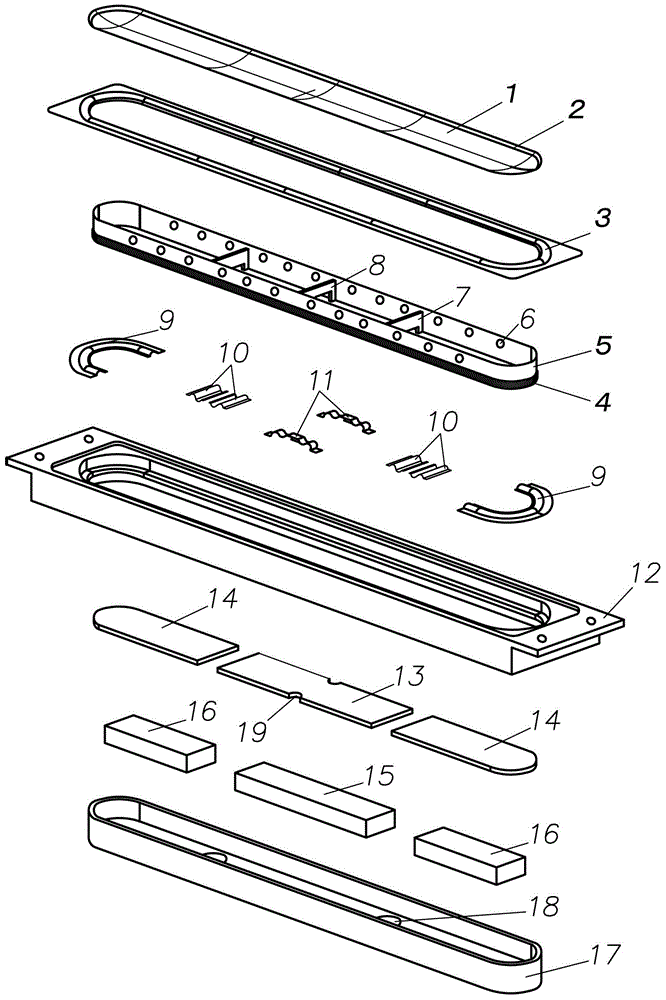
[0038] Hereinafter, the speaker of the present invention will be described in detail with reference to the drawings. figure 1 It is an exploded perspective view of a speaker according to one embodiment of the present invention. Such as figure 1 As shown, the loudspeaker includes a vibrating plate 1 as a paper cone, a rib 3, a voice coil 4, a voice coil bobbin 5, a support piece, a bracket 12, and a magnetic circuit structure. The support includes a first support 9 and a second support 10 . The magnetic circuit structure includes a yoke 17 , magnets 15 , 16 and iron sheets 13 , 14 . Note that in the following description, the speaker is mounted on the side of the diaphragm 1 ( figure 1 The middle and upper side) is called "upper side", and the side where the yoke 17 is installed ( figure 1 The lower side in ) is referred to as the "lower side".

[0039] Such as figure 1As shown, from the vibration direction of the vibration plate 1, the planar shape of the vibration plate...


PUM


Abstract

The invention provides a slender loudspeaker structure, which comprises a vibration plate (1), a baffle edge (3), a voice coil wire winding tube (5), a voice coil (4), a magnetic loop structure, a support sheet and a support frame (12) in the vibration direction, wherein the vibration plate (1) is provided with short edges and long edges, the inner edge of the baffle edge (3) is connected with the outer edge of the vibration plate (1), the upper part of the voice coil wire winding tube (5) is connected with the vibration plate (1), the inner side of the voice coil wire winding tube (5) is provided with reinforcing plates at intervals in the long edge direction, the voice coil (4) is coiled and wound on the voice coil wire winding tube (5), the magnetic loop structure comprises a magnetic yoke, an iron sheet and a magnet, a magnetic gap is formed between the magnetic yoke and the iron sheet, the voice coil is arranged in the magnetic gap, the support sheet is used for movably maintaining the voice coil wire winding tube (5) in the vibration direction, the support frame (12) is used for maintaining the outer edge of the baffle edge (3) and the magnetic loop structure, and the baffle edge (3) is connected with the lower surface side of the vibration plate (1). The invention can provide the slender thin loudspeaker with the improved tone quality performance.

Description

technical field [0001] The invention relates to a loudspeaker structure, in particular to an elongated thin loudspeaker structure with long sides and short sides. Background technique [0002] It has been hundreds of years since the speaker was invented. Although the principle of electro-acoustic conversion has not changed, with the progress of society, the speaker is required to be more and more miniaturized. Especially with the development of TV technology and fierce price competition, large and thin TVs are becoming more and more popular, which requires the speakers arranged on both sides to be thin and slender. TVs over 40 inches are very common in the market today, but none of them are equipped with speakers that can give full play to the sound effects. [0003] Various speakers have been researched in the prior art, but there are no speakers suitable for installation on both sides of a thin TV. Most of the speakers used in today's TVs have a short side of 35mm, a lon...

Claims


Application Information

Patent Timeline
Patent Type & Authority Applications(China)
IPC IPC(8): H04R9/06
Inventor 幅秀幸
Owner WUJIANG KAILIANDA METAL PROD
Learn More