Tube cleaner speed controller with hydraulic system

A speed controller, hydraulic system technology, applied in the direction of cleaning hollow objects, cleaning methods and utensils, chemical instruments and methods, etc., can solve the problem of expensive rental of pigs

Inactive Publication Date: 2015-03-25
SOUTHWEST PETROLEUM UNIV
View PDF6 Cites 28 Cited by
  • Summary
  • Abstract
  • Description
  • Claims
  • Application Information

AI Technical Summary

Problems solved by technology

Domestic bypass valve active control pigs are still immature, and overseas such pigs are expensive...

Method used


Image

  • Tube cleaner speed controller with hydraulic system
  • Tube cleaner speed controller with hydraulic system
  • Tube cleaner speed controller with hydraulic system

Examples


Embodiment Construction

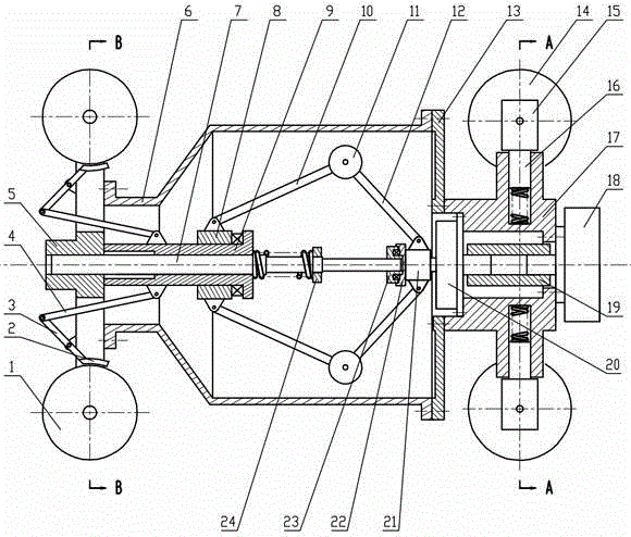
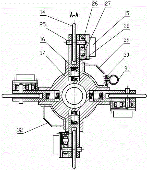
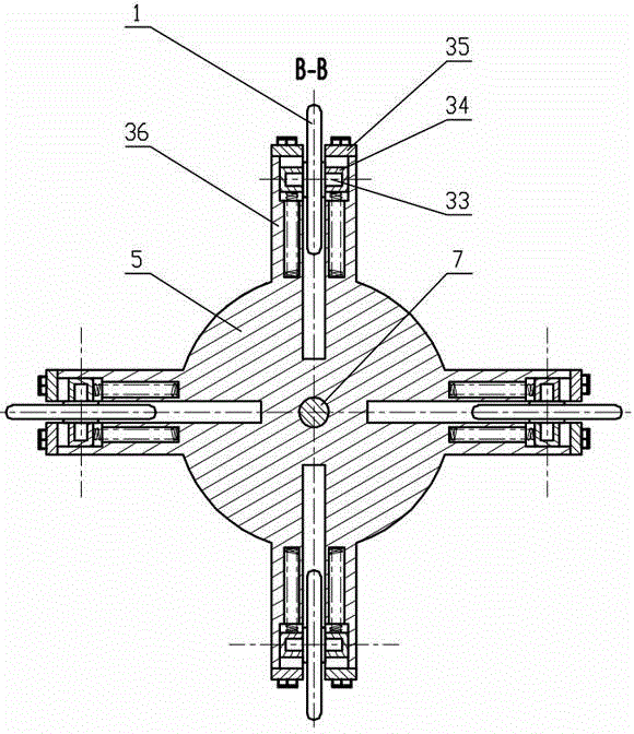
[0024] The present invention is not limited by the following implementation examples, and specific implementation manners can be determined according to the technical solutions of the present invention and actual conditions. Combine below figure 1 , 2 , 3 The present invention is described below. The positional relationship of up, down, left, right, etc. is based on the attached figure 1 determined by the layout direction.

[0025] Such as figure 1 As shown, the friction plate 2 is fixed on the end of the connecting rod A3, the middle of the connecting rod A3 is hinged to the rear end cover 5, the other end of the connecting rod A3 is hinged to the end of the connecting rod B4, and the other end of the connecting rod B4 is hinged to the fixed on cylinder 9. The fixed cylinder 9 is sleeved on the central shaft 7 and connected by splines, the fixed cylinder 9 is covered with the rotating cylinder 8, the end of the fixed cylinder 9 is provided with a step, and the rotating c...


PUM


Abstract

The invention relates to a tube cleaner speed controller with a hydraulic system. By means of the tube cleaner speed controller, the defects of a bypass valve control mode can be overcome. According to the technical scheme, front wheels are arranged on a base through supports and are arranged in the radial direction of the base, the lower ends of the supports are provided with compression springs, and the front wheels are connected with gear pumps; a radial plunger motor is arranged at the end of the base through a bolt, a speed changer is arranged at the center of the base, and an output shaft of the speed changer drives a mass block in a cylinder body to rotate; rear wheels are arranged on a rear end cover, the ends of connection rods A are fixedly provided with friction pieces, the friction pieces are closely attached to the outer edges of the rear wheels, the middle of each connection rod A is hinged to the rear end cover, the other end of each connection rod A is connected with the end of each connection rod B in a hinged mode, the other end of each connection rod B is hinged to a safety barrel, and the safety barrel is connected with a central shaft through a spline. The tube cleaner speed controller can be used just by being arranged on the rear side of a tube cleaner and can be suitable for various types of tube cleaning works.

Description

technical field [0001] The invention relates to a pig speed controller. Background technique [0002] In the process of pigging and testing oil and gas pipelines, general regulations require that the running speed of the pigging equipment is 3.5-5m / s; in order to obtain better quality of testing data, the running speed of the testing equipment in the pipeline is required to be lower than 5m / s ; Electromagnetic ultrasonic testing equipment requires its operating speed to be lower than 2m / s. The speed of the pigs changes greatly when passing through the uphill and downhill sections, curved sections, liquid accumulation, sand accumulation and fouling sections of the pipeline, and the direct use of conventional pigs cannot meet the speed control requirements. [0003] The speed control modes of existing oil and gas pipeline pigs are active control mode and passive control mode. [0004] The active control adopts the bypass valve control method, and its technical solution is: u...

Claims


Application Information

Patent Timeline
IPC IPC(8): B08B9/051
CPCB08B9/053B08B9/0551B08B2209/0553
Inventor 何虹钢张珍珍牛新科梁政叶哲伟
Owner SOUTHWEST PETROLEUM UNIV
Why Eureka
Try Eureka