

High rigidity deploy-in-position locking device
Patent Information
- Authority / Receiving Office
- CN · China
- Patent Type
- Patents(China)
- Current Assignee / Owner
- SHANGHAI AEROSPACE SYST ENG INST
- Publication Date
- 2017-01-18
Smart Images
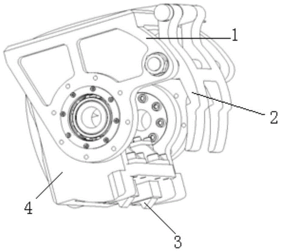
Figure 1 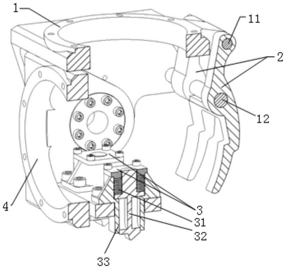
Figure 2 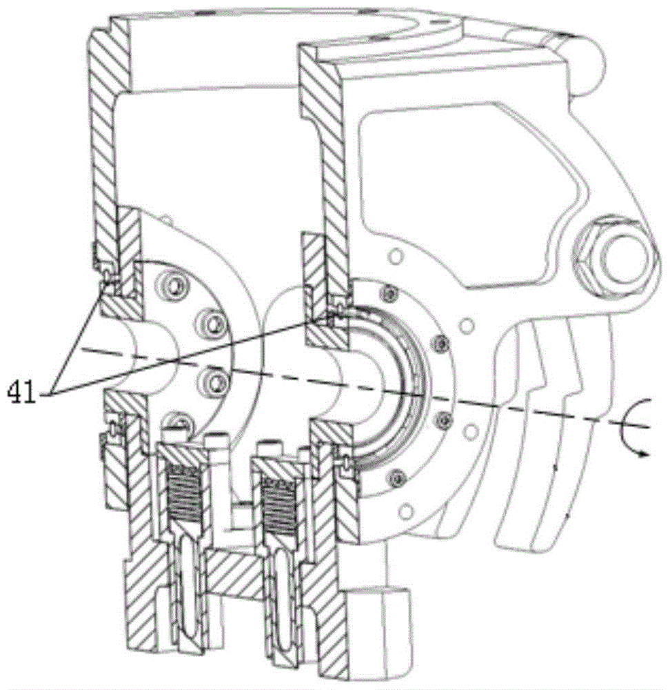
Figure 3
Abstract
Description
technical field
[0001] The invention relates to a locking device for an aerospace vehicle deployment mechanism, in particular to a high-rigidity deployment-in-position locking device for a solar battery wing and a satellite antenna deployment mechanism. Background technique
[0002] The solar battery wings and satellite antennas of aerospace vehicles need to be compressed before launch to overcome the vibration and shock load during the launch into orbit stage. on-orbit fundamental frequency.
[0003] At present, the deployment and locking methods commonly used by aerospace vehicles include self-locking worm gear methods and latch methods. The disadvantage of the worm gear method is that the working load is generally only a few tens of Nm, which cannot meet the needs of the large inertia load of hundreds to thousands of Nm to expand and lock, and under the influence of the load impact, a motion gap will gradually occur. The locking stiffness is reduced. In addition, due to...