A grid rudder deployment locking mechanism for space transport

A locking mechanism and grid rudder technology, applied in the direction of weapon types, offensive equipment, projectiles, etc., to achieve the effects of reducing the internal resistance of the mechanism, strong bearing capacity, and high locking rigidity

Active Publication Date: 2022-05-31
SHANGHAI AEROSPACE SYST ENG INST
View PDF7 Cites 0 Cited by
  • Summary
  • Abstract
  • Description
  • Claims
  • Application Information

AI Technical Summary

Problems solved by technology

[0006] The invention aims to solve the problem of deploying and locking the grid rudder of the space transporter with controllable landing area, and provides a locking mechanism for deploying the grid rudder suitable for the space transporter with controllable landing area

Method used


Image

  • A grid rudder deployment locking mechanism for space transport
  • A grid rudder deployment locking mechanism for space transport
  • A grid rudder deployment locking mechanism for space transport

Examples


Embodiment Construction

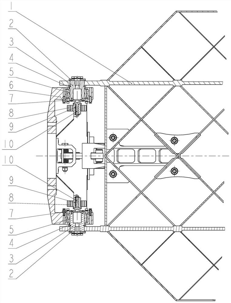
[0036] FIG. 5 is a schematic diagram of the spline connection structure between the spring inner end fixing member 9 and the spline shaft 10. Utilize a flat scroll

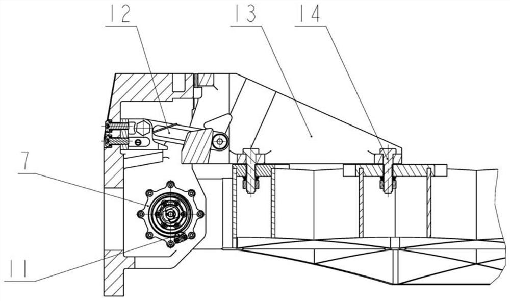
[0037] FIG. 6 is a schematic diagram of the structure of the locking lever assembly 12. The locking lever assembly 12 consists of a support 15, a gear lever 16, a torsion spring 17,

[0039] FIG. 9 is a schematic view of the structure of the locking track surface of the support rib 13. There are two sets of symmetrically arranged locks in the inner cavity of the support rib 13

[0040] FIG. 10 is a schematic diagram of the force analysis when the grid rudder 1 is subjected to a reverse rotational moment load in the external environment. Grid Rudder 1 Exhibition

[0043] The content that is not described in detail in the specification of the present invention belongs to the well-known technology of those skilled in the art.


PUM


Abstract

The invention relates to a grid rudder unfolding and locking mechanism for an aerospace transport vehicle, which uses a plane scroll spring to drive the grid rudder to unfold, uses the locking plane at the end of the support rib to cooperate with the locking plane on the base, and realizes the forward direction through mechanical limit. Locking, using the locking rod assembly to cooperate with the locking track surface in the inner cavity of the support rib, and realizing reverse locking through the principle of self-locking. The invention can realize the unfolding and locking of grid rudders driven and folded, and has beneficial effects such as simple structure, reliable deployment, high locking rigidity and strong bearing capacity, etc. The drop area control and fixed-point recovery provide technical support.

Description

A grid rudder deployment locking mechanism for space transporter technical field The present invention relates to the technical field of space transporter mechanisms, in particular to a kind of spaceflight transporter that is suitable for controllable drop zone The grid rudder deploys the locking mechanism. Background technique At present, my country's launch vehicle does not yet have the ability to control the sub-level drop area, and the distribution range of a sub-level drop area is generally 30% wide. km, 50 to 70 km long. At present, more than 20 to 30 space launch missions are carried out every year, and tens of thousands of people need to be evacuated each time. The wreckage destroyed houses, high-voltage lines, farmland, highways and other civilian facilities, polluted water sources, and provided safety to the lives and property of the people in the affected areas. It will cause serious harm and disrupt the normal life and production order. In addition, the...

Claims


Application Information

Patent Timeline
Patent Type & Authority Patents(China)
IPC IPC(8): F42B15/00F42B10/14
CPCF42B15/00F42B10/14
Inventor 宋佳袁伟顾珏华崔琦峰咸奎成陈雪巍金益辉秦伟沈蔚松
Owner SHANGHAI AEROSPACE SYST ENG INST
Why Eureka
Try Eureka