Cutter holder structure

A technology of knife handle and knife bar, which is applied in the field of clamping structure improvement, can solve the problems of limited shrinkage range, increased labor cost, limited application range of elastic collet 82, etc., and achieves the effect of increasing application range and high locking rigidity

Active Publication Date: 2020-09-04
张新添
View PDF12 Cites 0 Cited by
  • Summary
  • Abstract
  • Description
  • Claims
  • Application Information

AI Technical Summary

Problems solved by technology

[0002] Generally, a knife handle with an elastic collet is commonly used, such as Figure 10 , 11 Shown is an ER straight shank elastic collet tool holder, which is mainly used in the power turret of the processing machine or installed on the spindle of the processing machine. The tool handle 8 mainly includes a tool bar 81, and a clip is provided at the front end of the tool bar 81 The clamping structure includes the inner taper hole 811 at the front end of the cutter bar 81, and its content reaches an elastic collet 82, which can be used for a tool 6 with a straight handle (such as a milling cutter, a drill bit, a tapping cutter) in the elastic collet 82 ... etc.), and then locked by a nut 83, the nut 83 is used to force the elastic collet 82 to shrink and hold the tool 6, so as to quickly install and disassemble the tool 6; please refer to Figure 11 For example, for ER16 elastic collet, the diameter of the shank that can hold the tool ranges from 1 to 10mm. Each specification of the elastic collet 82 can hold a limited shrinkage range, and the size of the shank that can be clamped is affected by the elastic barrel. clamp limit, and the maximum clamping size of this collet structure can only reach 10mm, so the scope of application of a single elastic collet 82 is limited. Faced with increasingly complex and diverse processing environments, users must purchase more The size of the elastic collet is 82 so that it can cope with the ever-changing and diverse product processing
[0003] Known tool handles with elastic collets, the chuck structure design of the front end is mainly based on the elastic collet as the main clamping mechanism, and is matched with a nut to lock the knife bar of the tool. However, the elastic collet 82 of each specification can hold The contraction range is limited, and the user must purchase more elastic collets 82, which will only increase the labor cost

Method used


Image

  • Cutter holder structure
  • Cutter holder structure
  • Cutter holder structure

Examples


Embodiment Construction

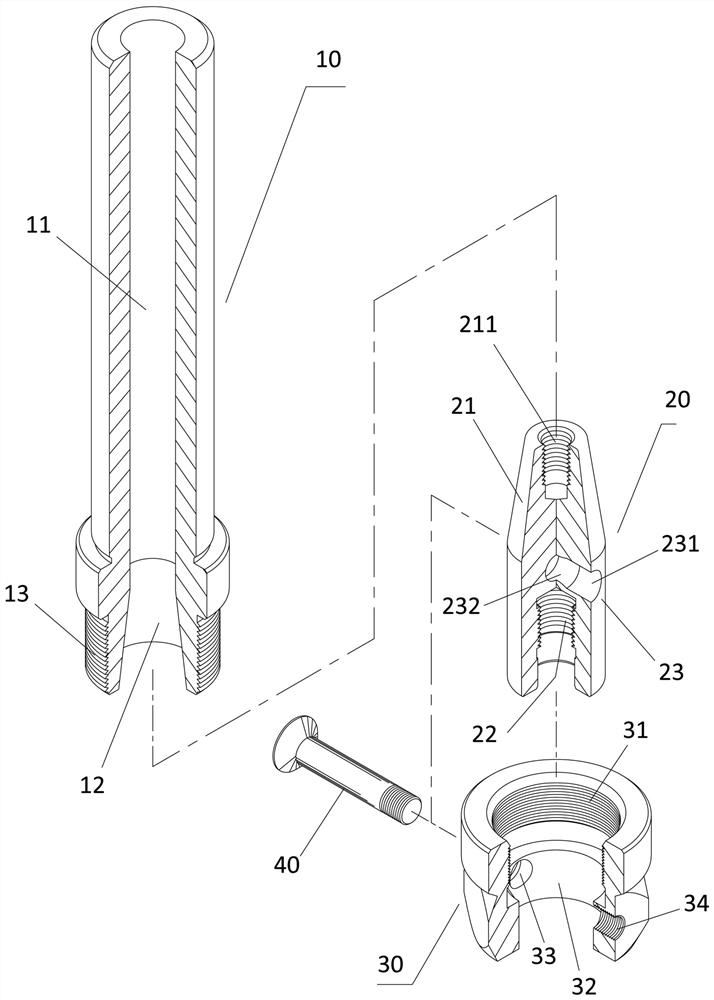
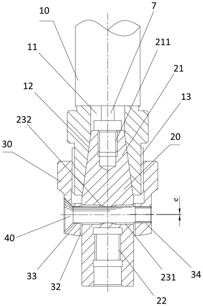
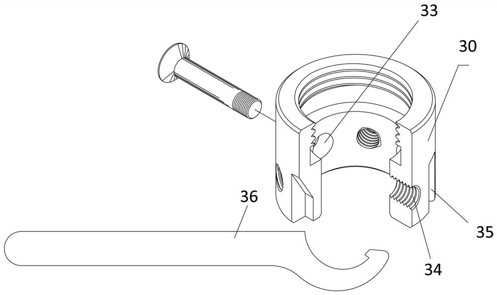
[0014] see figure 1 , 2 As shown, the knife handle structure of the present invention includes a knife bar 10, an adapter bar 20 and a nut 30, wherein:

[0015] Knife bar 10, as general commercially available straight shank knife bar or tapered shank knife bar, is provided with a through hole 11, and this through hole 11 front end is set as an inner tapered hole 12, and one end of this knife bar 10 is provided with outer thread 13;

[0016] Adapter rod 20, one end is provided with a tapered rod 21, and this tapered rod 21 corresponds to the inner tapered hole 12 of cutter bar 10, and the end face of described tapered rod 21 is provided with an inner threaded hole 211, which can be locked by tie rod bolt 7 , the other end of the adapter rod 20 is provided with another internal screw hole 22, which can be used for locking the cutter head 50 of a cutter such as a milling cutter or a drill bit (such as Figure 5 As shown), the adapter rod 20 is adjacent to the tapered rod 21 a...


PUM


Abstract

A cutter holder structure comprises a cutter arbor and a connecting shaft having a tapered section at one end thereof. One end of the tapered section is formed with a first inner screw hole, and another end of the tapered section is formed with a second inner screw hole. The connecting shaft further has a horizontal positioning hole that penetrates through the connecting shaft. Two ends of the positioning hole are formed with cylindrical holes. A reduced hole is defined between the cylindrical holes. A nut has a third inner screw hole at one end and an axial hole at another end. The nut further has a horizontal countersink hole and a horizontal fourth inner screw hole. An eccentric distance (e) is defined between a center of the countersink hole and a center of the fourth inner screw hole.A screw is inserted through the countersink hole and locked into the fourth inner screw hole.

Description

technical field [0001] The invention is an improved clamping structure of a knife handle, especially an improved knife handle clamping the limitation of the size of a knife, which has a knife handle structure with high locking rigidity and the same knife bar can replace different sizes of knife heads. Background technique [0002] Generally, a knife handle with an elastic collet is commonly used, such as Figure 10 , 11 Shown is an ER straight shank elastic collet tool holder, which is mainly used in the power turret of the processing machine or installed on the spindle of the processing machine. The tool handle 8 mainly includes a tool bar 81, and the front end of the tool bar 81 is provided with a clip The clamping structure includes the inner taper hole 811 at the front end of the cutter bar 81, and its content reaches an elastic collet 82, which can be used for a tool 6 with a straight handle (such as a milling cutter, a drill bit, a tapping cutter) in the elastic collet...

Claims


Application Information

Patent Timeline
Patent Type & Authority Applications(China)
IPC IPC(8): B23Q3/00B23B29/04
CPCB23Q3/00B23B29/04B23B31/11B23B31/1122B23B51/123B23B2231/0204B23B2231/04B23B2260/026B23B2260/082B23B2260/106B23B2265/08B23B2265/12F16B7/042B23B31/1072B23B31/1075
Inventor 张新添
Owner 张新添
Why Eureka
Try Eureka