Locking device

A locking device and lock nut technology, which is applied in the direction of building fastening devices, wing leaf fastening devices, buildings, etc., can solve the problems of spring elongation and locking state, increased replacement cost, spring elongation effectiveness, etc. , to achieve the effect of easy assembly and disassembly, low cost of use, and improved stability

Inactive Publication Date: 2015-03-25
ANHUI UNIVERSITY OF TECHNOLOGY AND SCIENCE
View PDF8 Cites 2 Cited by
  • Summary
  • Abstract
  • Description
  • Claims
  • Application Information

AI Technical Summary

Problems solved by technology

[0004] In order to overcome the existing locking device, when the locking device is in the locked state, the internal spring is in an elongated or compressed state; when the locking device is in an open state, the internal spring is in the original state; the locking device is locked most of the time In a tight state, the spring is in an elongated or compressed state for a long time and produces actual effects, which increases the replacement cost; the spring of the locking device is in an elongated or compressed state for a long time, resulting in defects such as an unstable locking state. The present invention provides a new Locking device

Method used


Image

  • Locking device
  • Locking device
  • Locking device

Examples


Embodiment Construction

[0011] Below in conjunction with accompanying drawing and embodiment the patent of the present invention is described further.

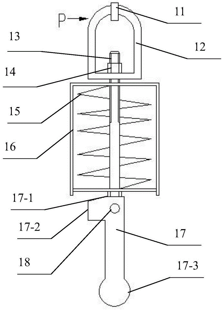
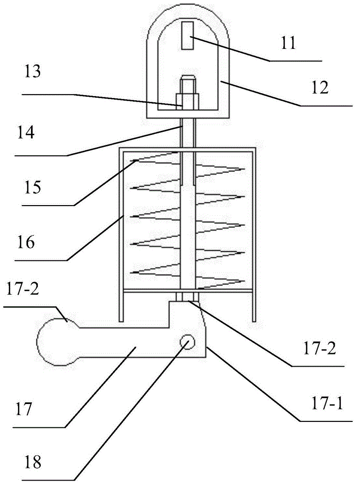
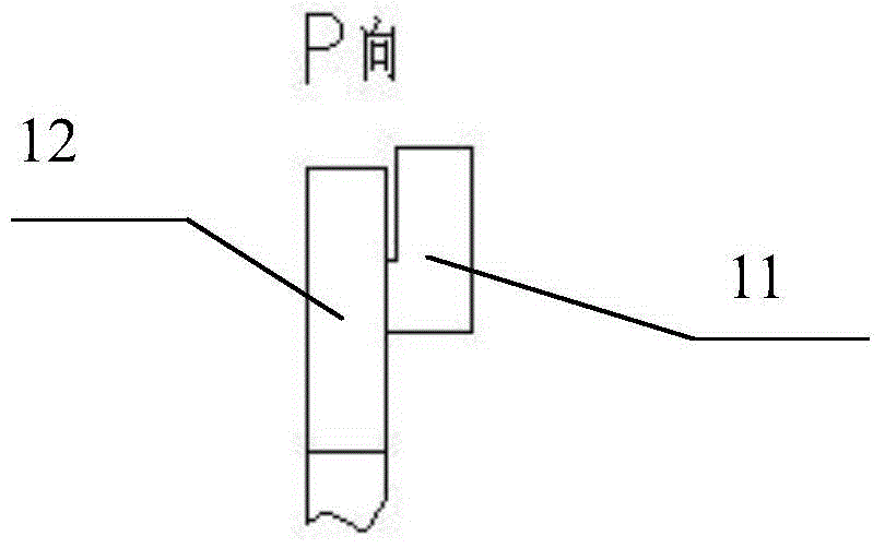
[0012] Referring to the accompanying drawings, a locking device includes a hook 11, a hanging ring 12, a long bolt 13, a lock nut 14, a spring 15, a connecting frame 16, an operating handle 17, a short boss of the operating handle 17-1, an operating handle The high boss place 17-2, the handle 17-3 of the operating handle, and the rotating shaft 18. Wherein, the shape of the hook 11 is L-shaped, which is a metal material, and is fixed on one of the doors of the box body that opens the door left and right or up and down; the front end of the long bolt 13 has a thread of sufficient length; the long bolt 13 passes through the connecting frame 16, The spring 15 and the hanging ring 12 are connected as one by the locking nut 14; the operating handle 17 is assembled on the rotating shaft 18 and rotates around the rotating shaft 18; Draw), be fixed on the o...


PUM


Abstract

The invention discloses a locking device. The locking device comprises a hook, a suspension loop, a long bolt, a locking nut, a spring, a connection frame, an operation handle and a rotary shaft, wherein the hook is fixed on a door of a box body; the long bolt penetrates through the connection frame, the spring and the suspension loop, and is connected with the connection frame, the spring and the suspension loop by the locking nut to form a whole body; the operation handle can rotate around the rotary shaft; the connection frame and the rotary shaft are connected to form a whole body and are fixed on the other door; a handholding part of the operation handle is lifted (pushed) upwards and the operation handle is rotated to be in a horizontal state; a high lug boss of the operation handle is arranged vertically and upwards; the bottom of an inner ring of the suspension loop is slightly higher than the top of the hook; the suspension loop sleeves the hook; the handholding part of the operation handle is pressed down and the operation handle is rotated to be in a vertical state; and a low lug boss of the operation handle is arranged vertically and upwards and the hook is tightly pulled by the suspension loop. When the locking device is in a locked state, the spring is in an original state; and when the locking device is in an unlocked state, the spring is in a compressed state. The locking device is simple in structure, convenient to operate, simple and convenient to mount and dismount, safe and reliable and low in use cost; and the stability is high when the locking state is in the locked state.

Description

Technical field [0001] The invention relates to the technical field of fastening devices, in particular to a locking device. Background technique [0002] In some cabinets with left and right doors or up and down doors, such as the left and right doors or up and down doors of the compartments of trucks, containers, cargo boxes, etc., the door needs to be locked after it is closed; and the door is locked most of the time. [0003] At present, in the existing locking device, when the locking device is in the locked state, the internal spring is in the elongated or compressed state; when the locking device is in the open state, the internal spring is in the original state; most of the time the locking device is in the The locked state causes the spring to be in an elongated or compressed state for a long time to produce real effects, which increases the replacement cost; the spring of the locking device is in an elongated or compressed state for a long time, resulting in an uns...

Claims


Application Information

Patent Timeline
Patent Type & Authority Applications(China)
IPC IPC(8): E05C19/14
Inventor 贾文友贾昊瑞刘莉何慧娟谢婉君
Owner ANHUI UNIVERSITY OF TECHNOLOGY AND SCIENCE
Why Eureka
Try Eureka