
Power supply device

a power supply device and power supply technology, applied in the direction of secondary cell servicing/maintenance, cell components, sustainable manufacturing/processing, etc., can solve the problems of increasing replacement cost or the like, and achieve the effect of increasing replacement cost, easy disassembly and assembly, and easy and separately replacemen

Inactive Publication Date: 2015-04-02
YAZAKI CORP
View PDF0 Cites 1 Cited by
  • Summary
  • Abstract
  • Description
  • Claims
  • Application Information

AI Technical Summary

Benefits of technology

The present invention aims to provide a power supply device that can easily and separately replace the battery assembly and the battery coupling block body, which solves the problem of increasing replacement cost.

Problems solved by technology

Therefore, both of the battery assembly 101 and the battery coupling block body 110 are integrally replaced and a problem of increasing replacement cost or the like occurred.

Method used


Image

  • Power supply device
  • Power supply device
  • Power supply device

Examples


Embodiment Construction

[0022]Hereinafter, an embodiment of the present invention will be described on the basis of the drawings.

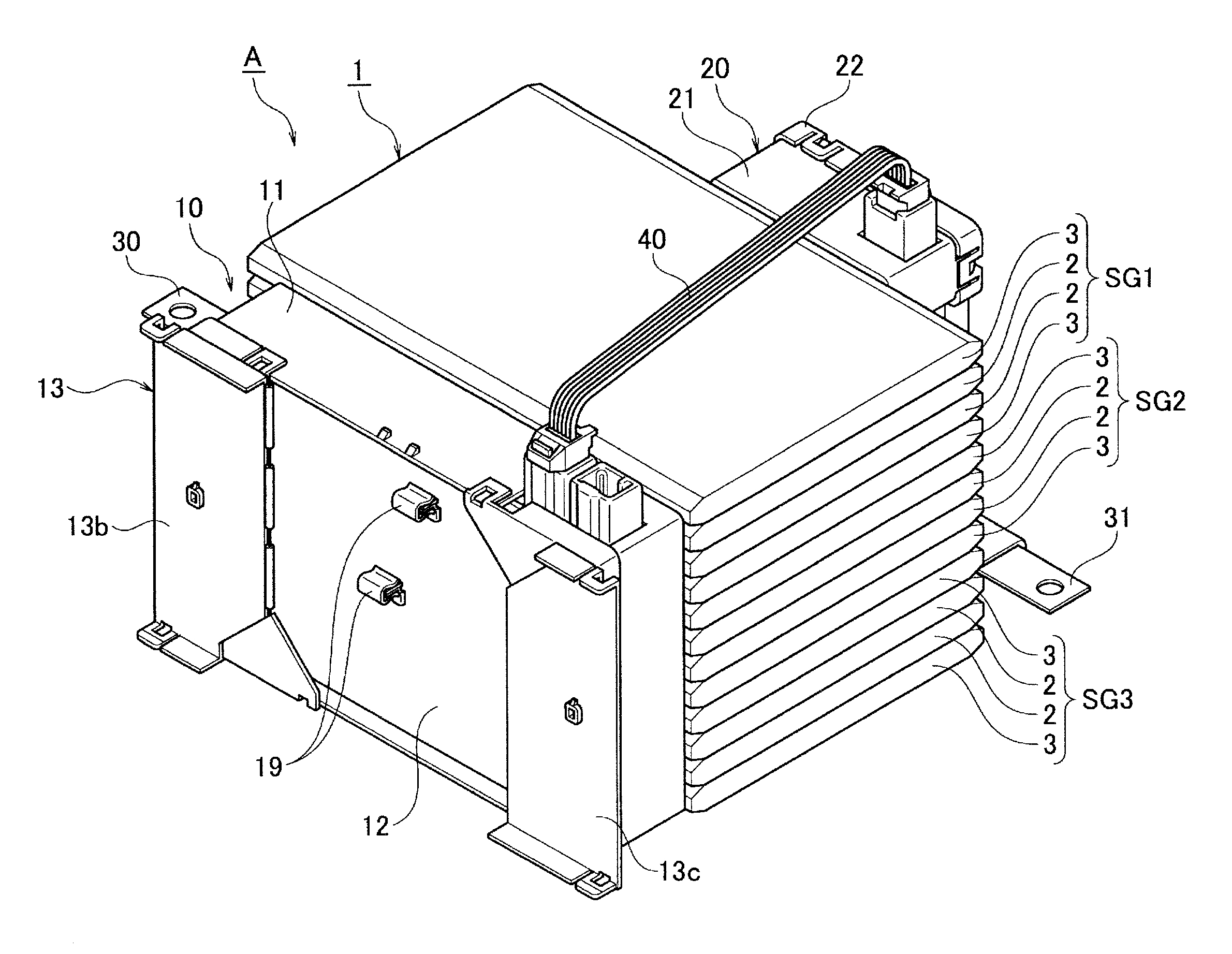
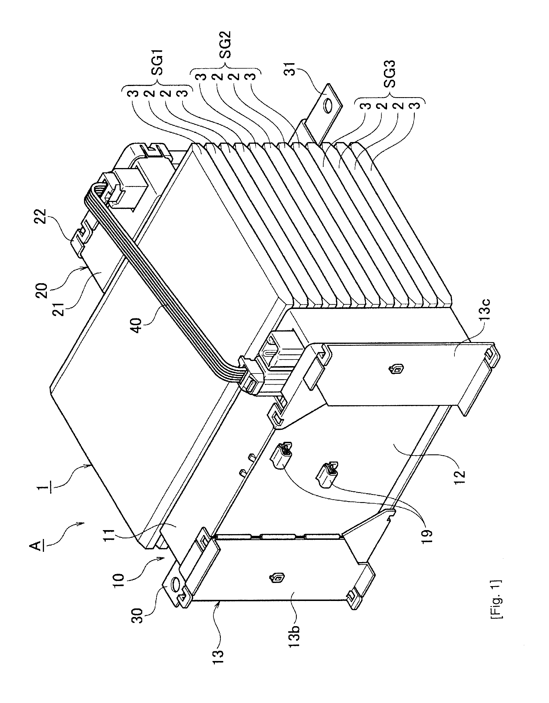
[0023]FIG. 1 to FIG. 10 show one embodiment of the present invention. As shown in FIG. 1, a power supply device A includes a battery assembly 1 including a plurality (twelve) of stacked battery cells 2 and 3, one pair of battery coupling block bodies 10 and 20 disposed on both sides of this battery assembly 1, and a flat cable 40 connected between the one pair of battery coupling block bodies 10 and 20.

[0024]The battery assembly 1, as shown in detail in FIG. 3, is constituted by the twelve battery cells 2 and 3. The battery assembly 1 is divided into three sets of battery cell groups SG1, SG2 and SG3 in which four battery cells 2 and 3 are parallel-connected, and the three sets of battery cell groups SG1, SG2 and SG3 are series-connected.

[0025]As shown in FIG. 4(a), the battery cell 2 has a flat rectangular cell body 2a, and one pair of electrodes (plus electrode and minus electr...


PUM

PropertyMeasurementUnit
electrically coupledaaaaaaaaaa
voltageaaaaaaaaaa
connection structureaaaaaaaaaa

Abstract

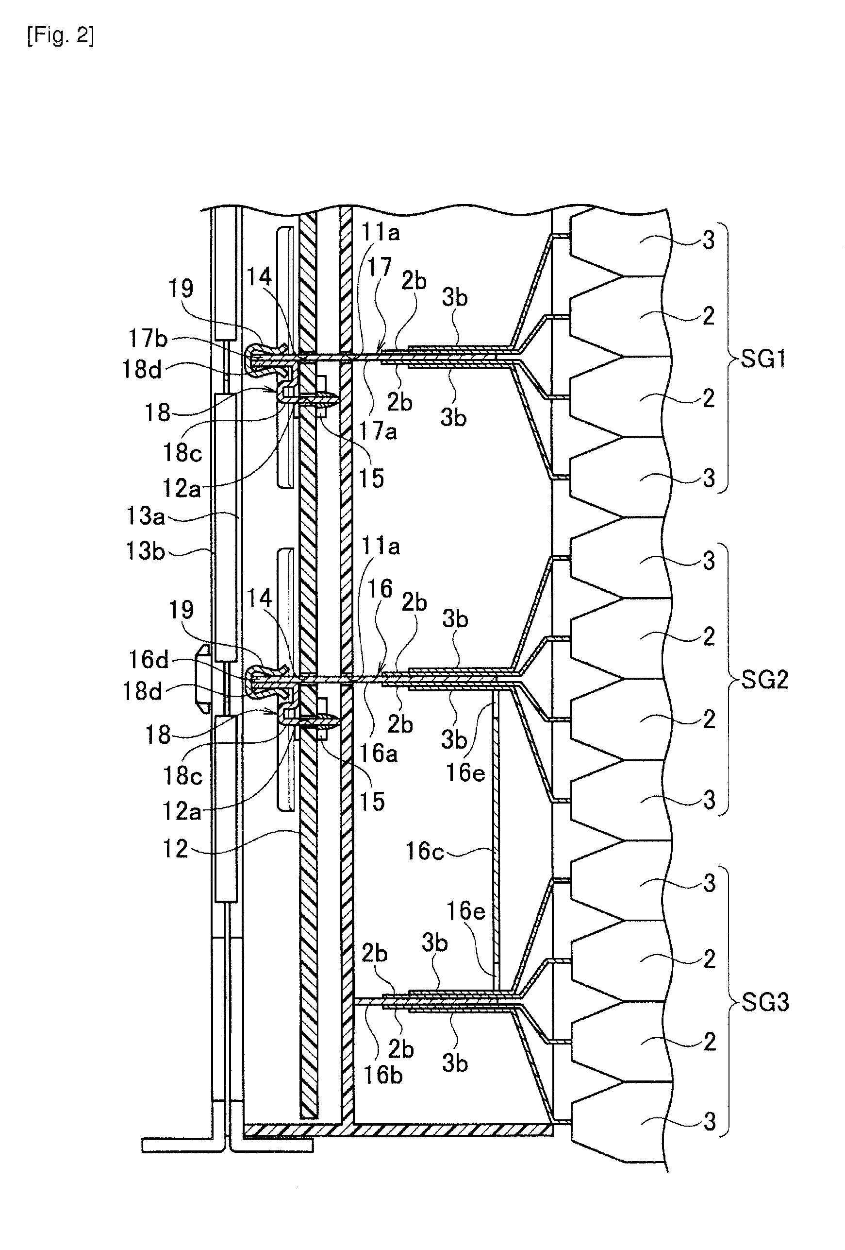
A power supply device (A) comprising a battery assembly (1) in which a plurality of battery cells (2) and (3) having electrodes (2b) and (3b) projected is stacked, a battery coupling block body (10) disposed on a side of the battery assembly (1) where the electrodes (2b) and (3b) are projected and having a substrate (12) provided with a circuit pattern part for voltage detection and provided with a terminal insertion hole (14), battery-side-relay terminals (16) and (17) connected to the electrodes (2b) and (3b) of the battery cells (2) and (3) and projected from the terminal insertion holes (14) to an outer surface side of the substrate (12), a substrate-side-relay terminal (18) connected to the circuit pattern part for voltage detection and projected to the outer surface side of the substrate (12) and clips (19) clamping both of the battery-side-relay terminals (16) and (17), and the substrate-side-relay terminal (18).

Description

TECHNICAL FIELD[0001]The present invention relates to a power supply device having a plurality of stacked battery cells.BACKGROUND ART[0002]A power supply device is mounted, for example, on a hybrid vehicle or an electric vehicle as a driving source for an electric motor. Up to now, various power supply devices have been proposed (see Patent Literatures, PTL 1 and 2), and also the present applicant has proposed a power supply device shown in FIG. 11.[0003]As shown in FIG. 11, this power supply device 100 includes a battery assembly 101 which has a plurality of stacked battery cells 102 and 103 and in which respective electrodes 102b and 103b of the adjacent battery cells 102 and 103 are disposed facing each other, and a battery coupling block body 110 disposed on a side of the battery assembly 101 where the electrodes 102b and 103b are projected.[0004]The battery coupling block body 110 includes an insulating case body 111, a relay terminal 112 fixed to this insulating case body 111...

Claims


Application Information

Patent Timeline
Patent Type & Authority Applications(United States)
IPC IPC(8): H01M2/10H01M10/48H01M2/30H01M50/209H01M50/249H01M50/284H01M50/512H01M50/516H01M50/519H01M50/548H01M50/553
CPCH01M2/1072H01M10/482H01M2/305H01M10/0413H01M10/425H01M10/0481H01M50/548H01M50/284H01M50/249H01M50/512H01M50/553H01M50/209H01M50/519H01M50/516Y02E60/10Y02P70/50
Inventor YOSHIOKA, NOBUAKI
Owner YAZAKI CORP
Learn More