
Yarn guiding roller which is connected through rotary insertion and is for textile printing and dyeing machine

A technology of textile printing and dyeing and yarn delivery rollers, which is applied in the field of yarn delivery rollers, which can solve the problems of affecting the normal operation of yarn printing and dyeing, increasing costs, deformation of yarn delivery rollers, etc., so as to facilitate individual replacement, reduce costs and waste of resources Effect

Inactive Publication Date: 2018-11-16
DONGGUAN LIANZHOU INTPROP OPERATION MANAGEMENT CO LTD
View PDF0 Cites 1 Cited by
  • Summary
  • Abstract
  • Description
  • Claims
  • Application Information

AI Technical Summary

Problems solved by technology

[0002] Printing and dyeing is a comprehensive process of physical and chemical treatment of textiles. Many yarn delivery rollers are used to prevent printing and dyeing machinery. After a long period of use, yarn delivery rollers are easily deformed due to external forces. , affecting the normal operation of yarn printing and dyeing, but the existing yarn delivery roller is often deformed and damaged by the roller body, but the entire yarn delivery roller needs to be replaced as a whole, which causes waste of resources and increases cost expenditure

Method used

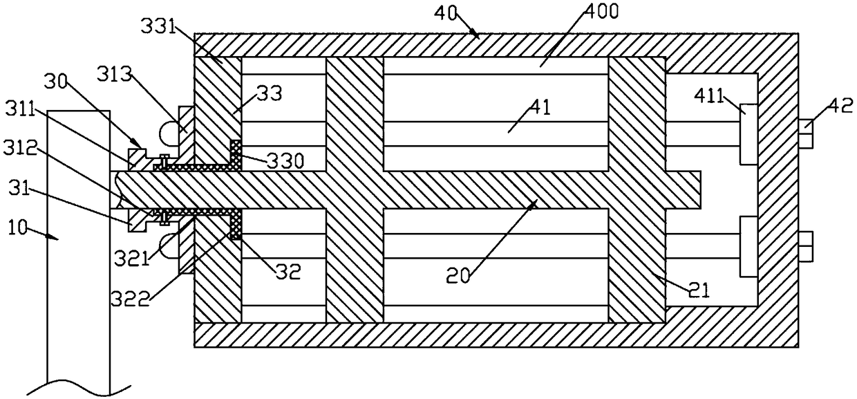
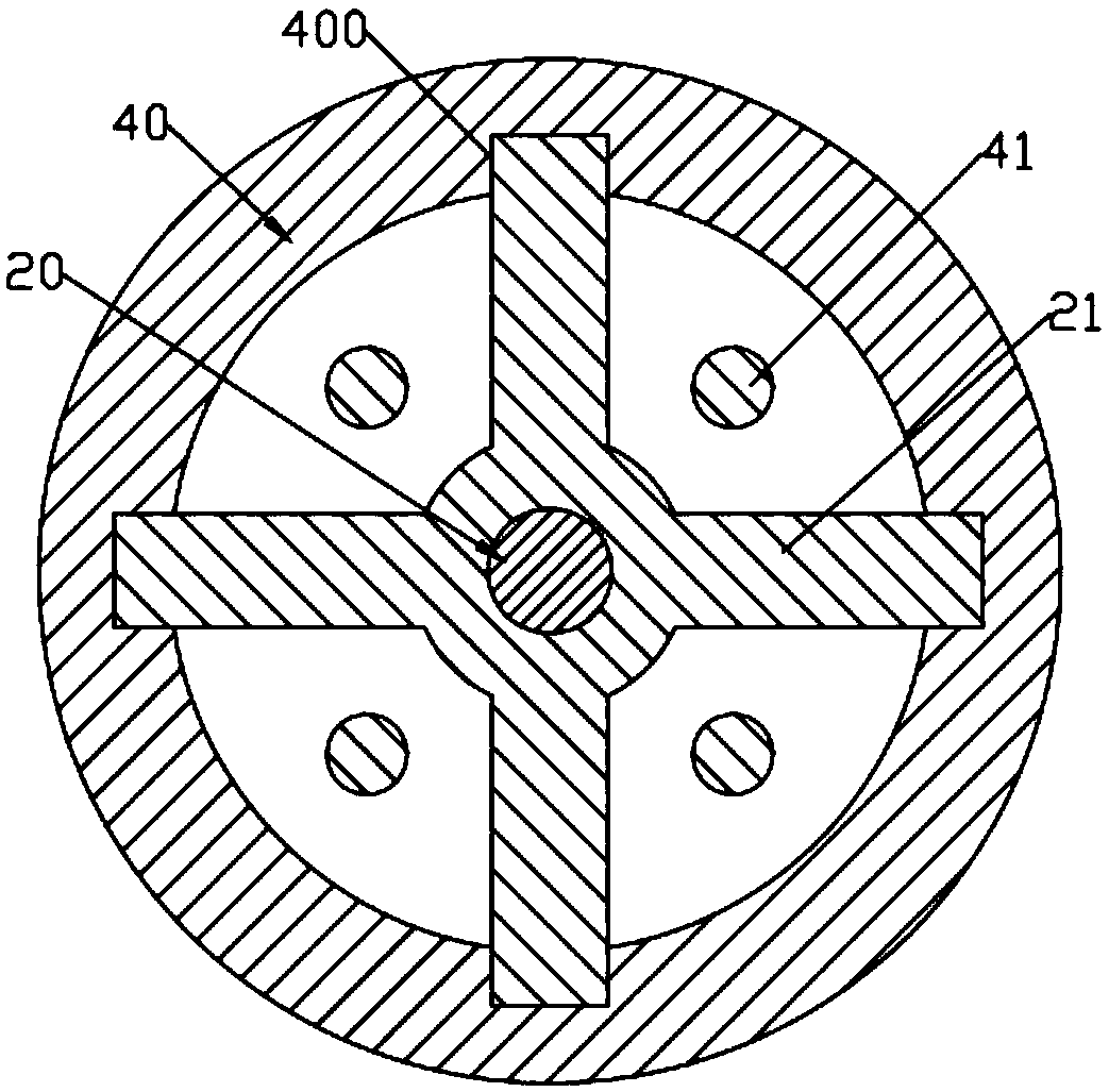
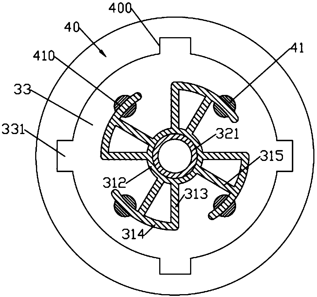

Image

  • Yarn guiding roller which is connected through rotary insertion and is for textile printing and dyeing machine
  • Yarn guiding roller which is connected through rotary insertion and is for textile printing and dyeing machine
  • Yarn guiding roller which is connected through rotary insertion and is for textile printing and dyeing machine

Examples


Embodiment Construction

[0016] Such as Figure 1 ~ Figure 3 As shown, a yarn drawing roller for textile printing and dyeing machinery is connected by rotation and insertion, including a support plate 10, a rotation shaft 20, a limit connection device 30 and a roller body 40; the left end of the rotation shaft 20 is pivotally connected to the support plate 10; The left part of the rotating shaft 20 is formed with several cross-shaped guide blocks 21 and all the guide blocks 21 are overlapped left and right; the inside of the roller body 40 is hollow and the left end is not sealed; the inner cavity of the roller body 10 is in the shape of a cylindrical groove; The side wall of the inner chamber is formed with four uniform guide grooves 400 that cooperate with the guide block 21 and the left end of the guide groove 400 is not sealed; The distribution of limit connecting rods 41; the limit connecting rods 41 and the guide groove 400 are staggered; the limit connecting device 30 includes a limit connectin...


PUM


Abstract

The invention discloses a yarn guiding roller which is connected through rotary insertion and is for a textile printing and dyeing machine. The yarn guiding roller comprises a support plate, a rotaryshaft, a limiting connecting device and a roller body; several cross guiding blocks are formed at the left part of the rotary shaft; an inner cavity of the roller body is in a cylindrical groove shape; four guiding grooves which are uniform circumferentially are formed in the side wall of the inner cavity of the roller body; four limiting connecting rods which are uniformly distributed circumferentially move on the right side wall of the inner cavity of the roller body left and right; the limiting connecting device comprises a limiting connecting unit which is pivoted to the left end of the rotary shaft; an annular limiting plate is detachably and rotatably arranged on the right end face of the limiting connecting unit; the limiting connecting unit comprises four cylindrical inserted limiting insertion rods which synchronously rotate; arc limiting insertion holes for the inserted limiting insertion rods to penetrate through are formed in the front ends of the limiting connecting rods.The yarn guiding roller is simple in structure and detachable; the roller body which is easily damaged is convenient to replace independently, the waste of resources is reduced, and the cost expenditure is reduced.

Description

technical field [0001] The invention relates to the technical field of textile printing and dyeing machinery, in particular to a spinning roller for textile printing and dyeing machinery that is connected by rotary insertion. Background technique [0002] Printing and dyeing is a comprehensive process of physical and chemical treatment of textiles. Many yarn delivery rollers are used to prevent printing and dyeing machinery. After a long period of use, yarn delivery rollers are easily deformed due to external forces. , affecting the normal operation of yarn printing and dyeing, but the existing yarn-drawing roller is often deformed and damaged by the roller body, but the whole yarn-drawing roller needs to be replaced as a whole, which causes a waste of resources and increases costs. Contents of the invention [0003] The purpose of the present invention is to address the deficiencies in the prior art, and provide a spinning roller for textile printing and dyeing machinery,...

Claims


Application Information

Patent Timeline
Patent Type & Authority Applications(China)
IPC IPC(8): D06B23/04
CPCD06B23/04
Inventor 徐亚维
Owner DONGGUAN LIANZHOU INTPROP OPERATION MANAGEMENT CO LTD
Learn More