Electric push rod capable of only pushing but not pulling

An electric push rod and screw technology, applied in the field of mechanical device transmission, can solve the problems of high risk, low safety performance, easy to be pinched, etc., and achieve the effects of convenient operation, improved safety performance and strong controllability

Pending Publication Date: 2020-03-27
ZHEJIANG JIECHANG LINEAR MOTION TECH
View PDF0 Cites 1 Cited by
  • Summary
  • Abstract
  • Description
  • Claims
  • Application Information

AI Technical Summary

Problems solved by technology

[0002] The electric push rod, also known as the linear drive, is mainly a linear actuator composed of a motor push rod and a control device. It can be used as an executive machine in various simple or complex processes to achieve remote control and centralized control. Control or automatic control, mainly used for motion drive units in industries such as household appliances, kitchen utensils, medical equipment, and automobiles. The electric push rod has exquisite design, small size, high precision, good self-locking performance, and hygiene. The structure specifically includes the drive motor, the socketed outer tube and inner tube, the threaded screw and the nut. The rod moves in the axial direction, which drives the expansion and contraction of the inner tube connected to the nut, and changes the rotational motion of the motor into a linear motion. The forward and reverse rotation of the motor is used to complete the push rod action, thereby driving the push and pull of the external movable platform connected to it. , so the inner tube expands and contracts closely with the movement of the nut. When the drive motor reverses to drive the inner tube to retract, it will not stop when it encounters foreign objects, which will easily cause damage to objects or human body, especially for curious children. , like to touch and explore with hands, it is easy to be pinched, the risk is high, and the safety performance is low

Method used


Image

  • Electric push rod capable of only pushing but not pulling
  • Electric push rod capable of only pushing but not pulling
  • Electric push rod capable of only pushing but not pulling

Examples


Embodiment

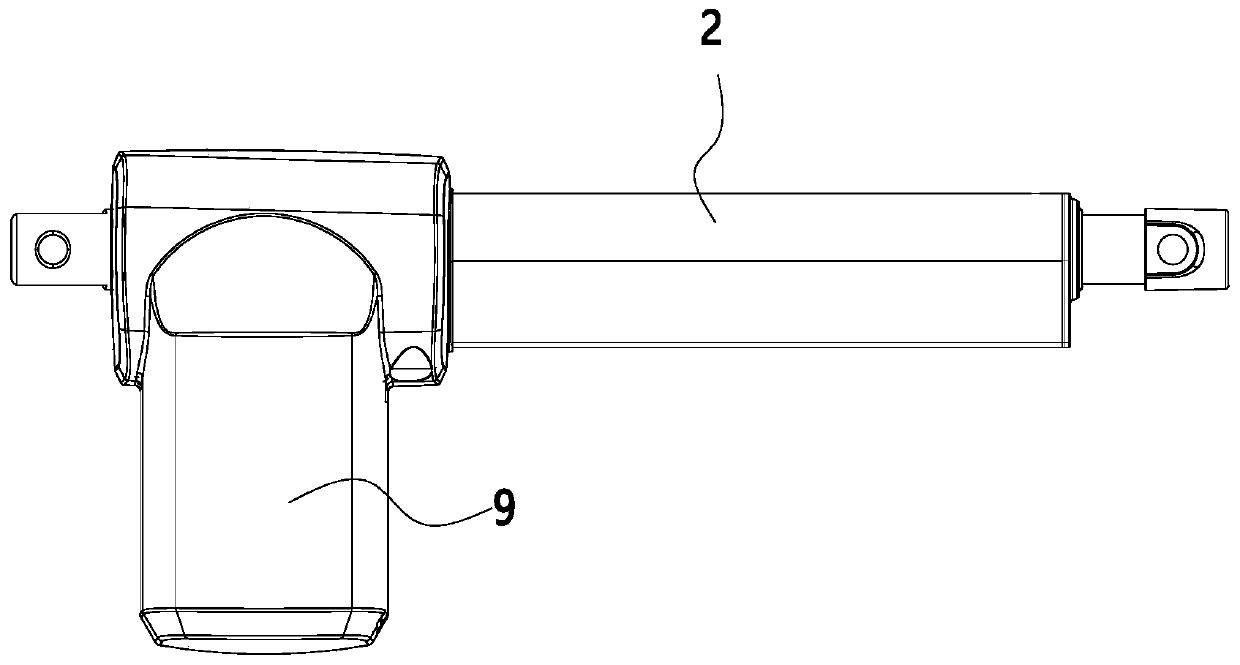
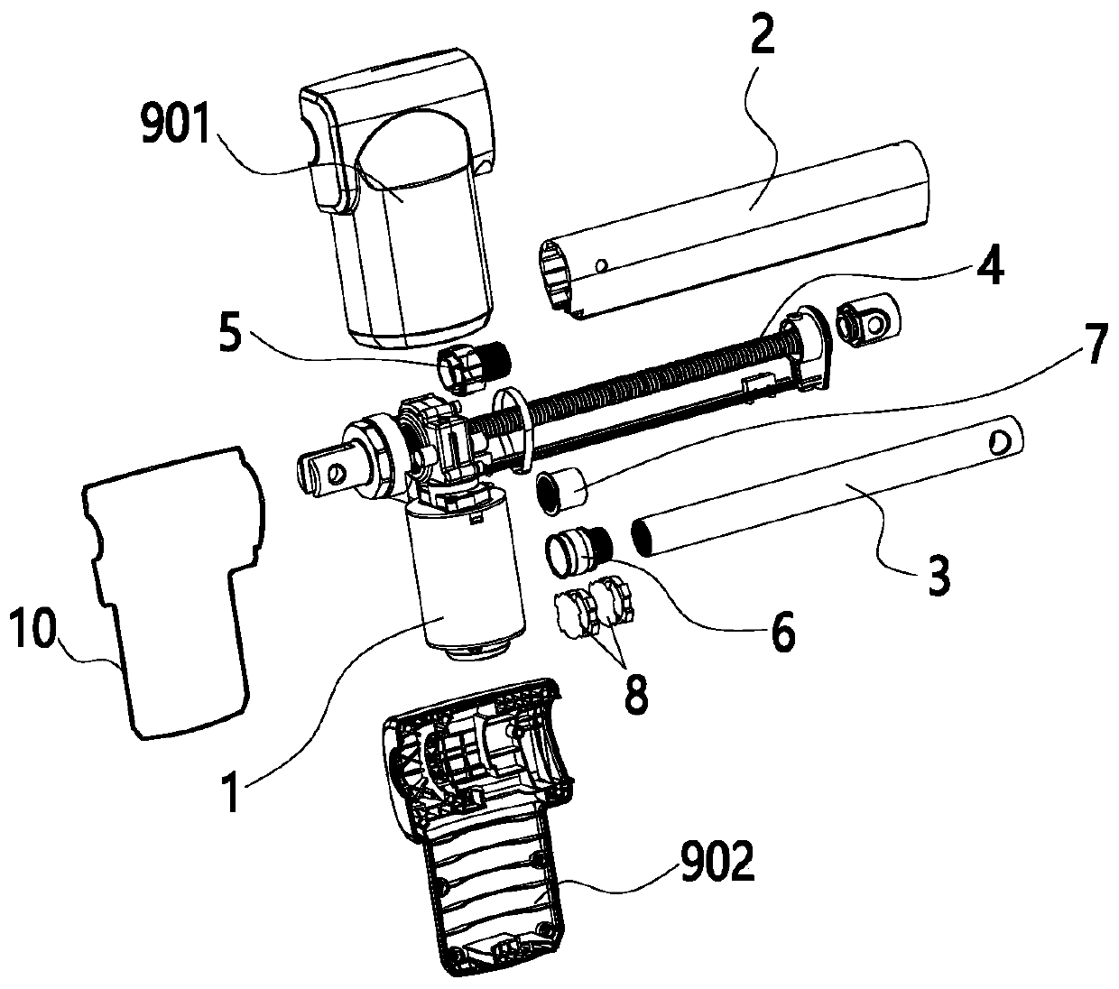
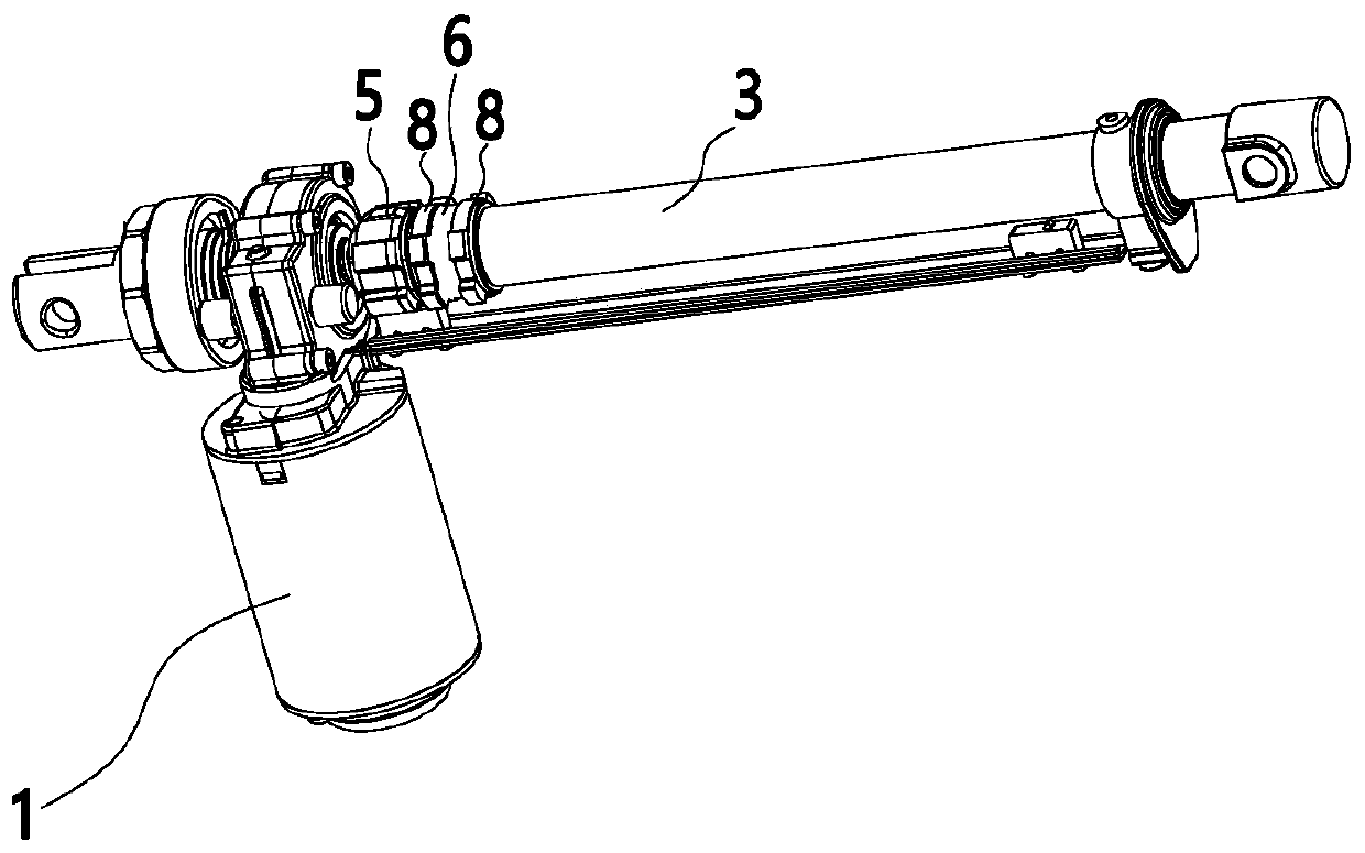
[0039] Such as Figure 1 to Figure 12 As shown, an electric push rod that only pushes but does not pull, the electric push rod includes a drive motor 1, an outer tube 2 fixedly connected to the drive motor 1 and an inner tube 3 sleeved in the outer tube 2, and the outer tube 2 is also provided with Driven by the drive motor 1, the screw 4 rotates and the nut 5 is sleeved on the screw 4 and moves along the axial direction of the screw 4. The drive motor 1 and the screw 4 are connected by transmission, and the inner tube 3 is provided with a coupling Set of 6, such as Image 6 As shown, the coupling sleeve 6 includes a first coupling portion 601 fixedly connected to the inner tube 3 , a second coupling portion 602 for slidingly sleeved on the nut 5 and a step connecting the first coupling portion 601 and the second coupling portion 602 part 603 , the coupling sleeve 6 bears the axial force on the nut 5 through the step part 603 .

[0040] When the drive motor 1 rotates forward...


PUM


Abstract

The invention discloses an electric push rod capable of only pushing but not pulling. The invention belongs to the technical field of mechanical device transmission. The electric push rod comprises adriving motor, an outer pipe fixedly connected with the driving motor and an inner pipe sleeved with the outer pipe, wherein a screw rod which is driven by a driving motor to rotate and a nut which issleeved on the screw rod and moves along the axial direction of the screw rod are also arranged in the outer pipe; a connecting sleeve is arranged on the inner pipe, and the connecting sleeve comprises a first connecting part fixedly connected with the inner pipe, a second connecting part used for being arranged on the nut in a sliding and sleeving mode and a step part connected with the first connecting part and the second connecting part; the connecting sleeve bears axial force on the nut through the step part; and the electric push rod is high in controllability, high in safety, capable ofsaving energy, environmentally friendly and high in stability.

Description

【Technical field】 [0001] The invention relates to the technical field of mechanical device transmission, in particular to an electric push rod that only pushes but does not pull. 【Background technique】 [0002] The electric push rod, also known as the linear drive, is mainly a linear actuator composed of a motor push rod and a control device. It can be used as an executive machine in various simple or complex processes to achieve remote control and centralized control. Control or automatic control, mainly used for motion drive units in industries such as household appliances, kitchen utensils, medical equipment, and automobiles. The electric push rod has exquisite design, small size, high precision, good self-locking performance, and hygiene. The structure specifically includes the drive motor, the socketed outer tube and inner tube, the threaded screw and the nut. The rod moves in the axial direction, which drives the expansion and contraction of the inner tube connected t...

Claims


Application Information

Patent Timeline
Patent Type & Authority Applications(China)
IPC IPC(8): H02K7/06
CPCH02K7/06
Inventor 胡仁昌陆小健何全胜
Owner ZHEJIANG JIECHANG LINEAR MOTION TECH
Why Eureka
Try Eureka