Insulation pipe connector

A technology for pipe joints and thermal insulation, which is applied in thermal insulation, pipe/pipe joints/pipe fittings, and protection of pipelines through thermal insulation, etc. It can solve the problems of fast heat transfer and heat dissipation, large amount of engineering, affecting the appearance of pipelines, etc., so as to reduce heat The effect of transferring and reducing heat loss

Inactive Publication Date:
View PDF8 Cites 4 Cited by
  • Summary
  • Abstract
  • Description
  • Claims
  • Application Information

AI Technical Summary

Problems solved by technology

In recent years, in order to reduce the heat loss in the heating pipeline, the surface of the pipeline is often wrapped with insulation materials, including pipe joints, switches, etc., are all covered with insulation materials to minimize heat loss, but this way The amount of work It is relatively large, and affects the appearance of the pipeline, and it is inconvenient to maintain. It has tended to be eliminated, so there have been a variety of transportation pipelines with thermal insulation functions. Through the layer-by-layer combination of new thermal insulation materials and pipelines, the effect of thermal insulation and product cost reduction is achieved
As the new technology is not updated, the products of thermal insulation pipes are relatively mature, but the pipe joints, which are an indispensable part of the pipe connection, also have the problem of fast heat transfer and heat dissipation, and people ignore them because they are only used at the pipe joints. However, if you add up all the pipe joints in a pipeline, you will find that the heat loss at the pipe joint is also a non-negligible part of the heat loss in the insulation pipeline.

Method used


Image

  • Insulation pipe connector
  • Insulation pipe connector
  • Insulation pipe connector

Examples


Embodiment Construction

[0015] The technical solution of the present invention is further described below in conjunction with the accompanying drawings, but the scope of protection is not limited to the description.

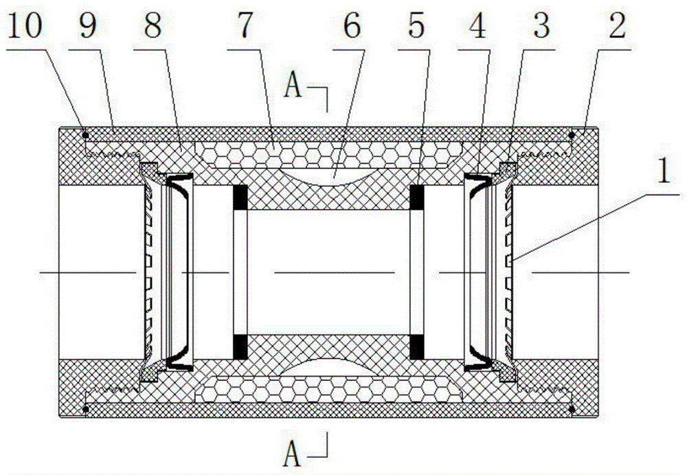
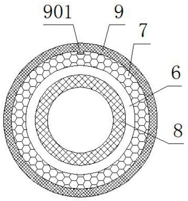
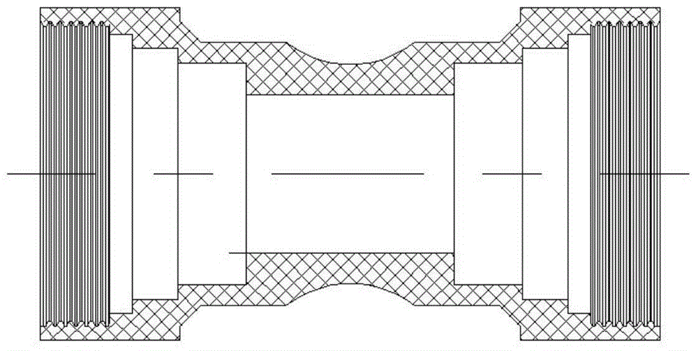
[0016] Such as figure 1 , figure 2 , image 3 , Figure 4 As shown, a pipe joint for heat preservation according to the present invention includes a spring washer 1, an end cap 2, a pipe sleeve 3, a sealing ring A4, a sealing ring B5 and an inner pipe body 8, and the end cap 2 and the inner pipe body 8 is movably connected, and the sealing ring A4, the sleeve 3 and the spring washer 1 are sequentially installed between the inner tube body 8 and the end cover 2. Tightly fixed, the sealing ring A4 is a bowl-shaped rubber sealing ring, and the spring washer 1 is made of stainless steel; the inner pipe body 8 is provided with an insulating layer 7, and the material of the insulating layer 7 is polyurethane foam. A cavity 6 is formed between the layer 7 and the inner tube body 8, and an...


PUM


Abstract

The invention discloses an insulation pipe connector and belongs to the technical field of water heating pipeline connection. The insulation pipe connector comprises an elastic cushion, an end cover, a pipe sleeve, a sealing ring A, a sealing ring B and an inner pipe body. The end cover is movably connected with the end cover, the sealing ring A, the pipe sleeve and the elastic cushion are sequentially installed between the inner pipe body and the end cover, the sealing ring B is located on a step end face in the inner pipe body, an insulation layer is arranged outside the inner pipe body and is made of polyurethane foaming plastic, a cavity is defined between the insulation layer and the inner pipe body, and an outer pipe body is further arranged outside the inner pipe body. According to the technical scheme, the insulation layer is arranged between the inner pipe body and the outer pipe body, meanwhile, the cavity is reserved between the inner pipe body and the insulation layer through the structural design of the inner pipe body, the double-insulation effect is achieved through insulation in a material isolation type and the insulation principle of an air convection prevention type, heat transfer is reduced to the maximum, and the heat loss at the pipe connector is reduced.

Description

technical field [0001] The invention belongs to the technical field of plumbing pipe connection, and relates to a pipe joint used for conveying heating, in particular to a heat-preserving pipe joint. Background technique [0002] With the gradual improvement of urban infrastructure, heating equipment such as heating and floor heating have entered thousands of households. The working principle of heating is that the hot water or steam burned by the boiler enters the radiator in the building through the pipe, and the heat is dissipated through the radiator. Into the indoor air, the indoor temperature rises to achieve the effect of heating, which is a form of thermal radiation heating. Hot water or steam in pipelines is usually called heating. After being heated in a centrally heated boiler room and other places, the heating needs to be transported through pipelines to the homes of households that need heating. destination. During the heating process, the heat loss is very la...

Claims


Application Information

Patent Timeline
Patent Type & Authority Applications(China)
IPC IPC(8): F16L59/18F16L37/088
CPCF16L37/088F16L59/182
Inventor 孔凡荣李志明
Why Eureka
Try Eureka