
Electric energy meter based on optical communication technology and circuit control method thereof

A circuit control and electric energy meter technology, applied in the direction of measuring electric variables, measuring devices, instruments, etc., can solve wiring troubles, high power consumption, lack of demand metering load curve, measuring voltage, current active power, apparent power And other issues

Inactive Publication Date: 2015-03-25
河南单点留学中介服务有限公司
View PDF0 Cites 1 Cited by
  • Summary
  • Abstract
  • Description
  • Claims
  • Application Information

AI Technical Summary

Problems solved by technology

[0002] Existing ordinary single-phase electric energy meters generally only have the functions of measuring electric energy and time-sharing multi-rate, and can display normally at low temperatures. Generally, LED digital tubes are used, with less display content and high power consumption.
In addition, the existing ordinary single-phase electric energy meters generally do not have the function of remote meter reading. Even the electric energy meters with remote meter reading function use wired transmission, the wiring is cumbersome, and generally do not have demand metering, event records, load curves, measurement Voltage, current, active power, apparent power, frequency, etc., detection of undervoltage, overvoltage, loss of current, overcurrent, etc.

Method used


Image

  • Electric energy meter based on optical communication technology and circuit control method thereof
  • Electric energy meter based on optical communication technology and circuit control method thereof

Examples


Embodiment Construction

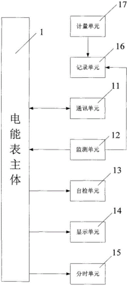
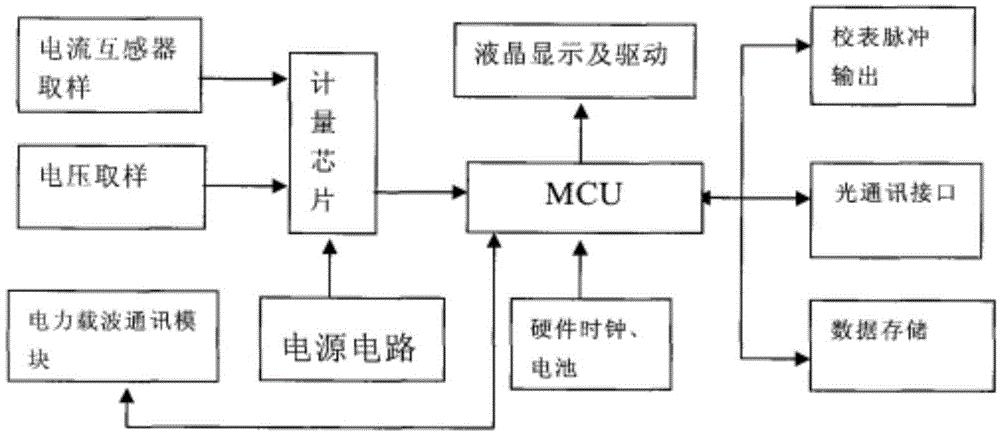
[0017] Attached below figure 1 , attached figure 2 The present invention is described in detail below.

[0018] Such as figure 1 As shown, the present invention comprises electric energy meter body 1, and its feature is: it also comprises on this electric energy meter body 1 respectively connects communication unit 11, monitoring unit 12, self-inspection unit 13, display unit 14 and time-sharing unit 15, and A recording unit 16 connected to the monitoring unit 12 and a metering unit 17 connected to the recording unit 16 .

[0019] The metering unit 17 is single-phase three-wire, on which a single transformer detects two currents, used for maximum demand metering, and has a large current and a wide metering range. The STPM01 chip produced by STMicroelectronics can be used.

[0020] The recording unit 16 is used to record electric energy, maximum demand, demand occurrence time, record electric energy and load curve, and record programming, time correction, demand clearing, ...


PUM


Abstract

The invention relates to the technical field of metering electric meters, and particularly relates to an electric energy meter based on an optical communication technology and a circuit control method thereof. The electric energy meter comprises a metering unit, a recording unit, a communication unit, a monitoring unit, a self-checking unit, a display unit and a timeshare unit. The metering unit is single-phase three-wire and meters the maximum demand, and is high in current and wide in metering range. The recording unit is used for recording electric energy, the maximum demand and demand generation time, recording a load curve and recording events of programming, time synchronization, demand zero clearing and time zone switching, etc. The communication unit is used for performing carrier communication on an automatic networking power line and providing optical port communication meeting an ANSI protocol. The monitoring unit is used for detecting power grid voltage, current, active power, apparent power and frequency. The self-checking unit is used for checking timeshare set errors and metering errors. The display unit is used for performing liquid crystal display normally at low temperature of -40 DEG C. The timeshare unit is used for meeting multi-rate timesharing of an ANSI standard. The invention provides the single-phase static electric energy meter which is more comprehensive in function and further adaptive to use demands of multilevel clients.

Description

technical field [0001] The invention relates to the technical field of metering electric meters, in particular to electric energy meters and circuit control methods based on optical communication technology. Background technique [0002] Existing ordinary single-phase electric energy meters generally only have the functions of measuring electric energy and time-sharing multi-rate, and can display normally at low temperatures. Generally, LED digital tubes are used, with less display content and high power consumption. In addition, the existing ordinary single-phase electric energy meters generally do not have the function of remote meter reading. Even the electric energy meters with the remote meter reading function still use wired transmission, the wiring is troublesome, and generally do not have demand metering, event records, load curves, measurement Voltage, current, active power, apparent power, frequency, etc., detection of undervoltage, overvoltage, loss of current, ov...

Claims


Application Information

Patent Timeline
Patent Type & Authority Applications(China)
IPC IPC(8): G01R22/06
Inventor 吴登国
Owner 河南单点留学中介服务有限公司
Learn More