
Display panel with touch function and manufacturing method of display panel

A display panel and manufacturing method technology, applied in the input/output process of data processing, optics, instruments, etc., can solve the problems of internal noise interfering with product yield, large thickness of touch panel, and limitation of light and thin display screen

Inactive Publication Date: 2015-03-25
TCL CHINA STAR OPTOELECTRONICS TECH CO LTD
View PDF4 Cites 5 Cited by
  • Summary
  • Abstract
  • Description
  • Claims
  • Application Information

AI Technical Summary

Problems solved by technology

[0003] Full bonding technology includes OGS technology dominated by touch screen manufacturers and On-Cell and In-Cell technologies dominated by display manufacturers. Compared with frame-mounted technology, OGS technology and On-Cell technology save a piece of glass And one-time bonding, so that the touch screen can be made thinner and lower cost, but the former needs to prepare a layer of touch sensor on the protective glass (that is, the transparent cover), and the latter needs to be on the CF glass substrate and its polarized light Make a layer of touch sensor between the chips. The thickness of the touch panel is relatively large, which limits the thinning of the display screen.
Although In-Cell technology can further achieve the goal of thinning by embedding the Touch sensor into the LCD, there are problems of internal noise interference and product yield.

Method used


Image

  • Display panel with touch function and manufacturing method of display panel
  • Display panel with touch function and manufacturing method of display panel

Examples


Embodiment Construction

[0019] The present invention will be described in detail below in conjunction with the accompanying drawings and embodiments.

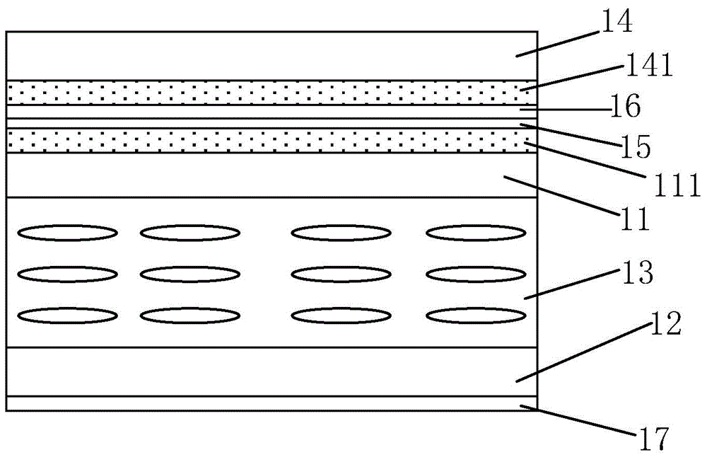
[0020] see figure 1 , figure 1 It is a structural schematic diagram of a preferred embodiment of the display panel with touch function of the present invention. In this embodiment, the display panel includes a first substrate 11, a second substrate 12, and a liquid crystal layer 13 sandwiched between the first substrate 11 and the second substrate 12, wherein the display panel further includes 11 The transparent cover 14 opposite to the surface away from the second substrate 12, the first touch electrode 111 formed on the surface of the first substrate 11 away from the second substrate 12, and the transparent cover 14 formed on the surface close to the first substrate 11 The second touch electrode 141 on the surface.

[0021] Preferably, the first touch electrodes 111 are sensing electrodes 111 , and the second touch electrodes 141 are driving elec...


PUM


Abstract

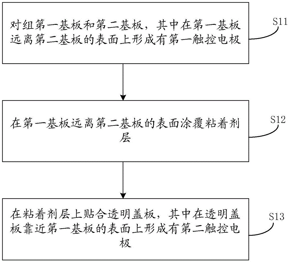
The invention discloses a display panel with a touch function and a manufacturing method of the display panel. The display panel comprises a first substrate and a second substrate which are oppositely arranged and a liquid crystal layer arranged between the first substrate and the second substrate, the display panel further comprises a transparent cover plate, a first touch electrode and a second touch electrode, the transparent cover plate is arranged oppositely to the surface, away from the second substrate, of the first substrate, the first touch electrode is formed on the surface, away from the second substrate, of the first substrate, and the second touch electrode is formed in the surface, close to the first substrate, of the transparent cover plate. By the above mode, the display panel with the touch function is further thinned and thinning of electronic equipment of cell phones and the like using the display panel are benefited.

Description

technical field [0001] The invention relates to the field of display technology, in particular to a display panel with a touch function and a manufacturing method thereof. Background technique [0002] With the increasingly fierce competition in the smart phone market, the structural design of small and medium-sized electronic products such as mobile phones has become one of the focuses of current mobile phone manufacturers, and an important solution to realize the thinner and lighter display screens of mobile phones is It is to replace the original frame sticker technology with full fit technology. [0003] Full bonding technology includes OGS technology dominated by touch screen manufacturers and On-Cell and In-Cell technologies dominated by display manufacturers. Compared with frame-mounted technology, OGS technology and On-Cell technology save a piece of glass And one-time bonding, so that the touch screen can be made thinner and lower cost, but the former needs to prep...

Claims


Application Information

Patent Timeline
Patent Type & Authority Applications(China)
IPC IPC(8): G02F1/1343G02F1/1333G06F3/041
CPCG02F1/13338G02F1/134309G06F3/0412G06F3/0445G06F2203/04103
Inventor 李曼黄耀立
Owner TCL CHINA STAR OPTOELECTRONICS TECH CO LTD
Learn More