
Electronic device

An electronic device and touch position technology, applied in the direction of electrical digital data processing, instruments, digital data processing components, etc., can solve problems such as difficult installation, complicated wiring, large volume, etc., and achieve the effect of reducing components

Inactive Publication Date: 2011-06-22
INVENTECSHANGHAI TECH
View PDF0 Cites 5 Cited by
  • Summary
  • Abstract
  • Description
  • Claims
  • Application Information

AI Technical Summary

Problems solved by technology

Although there is already a detachable touch screen, which uses a camera lens to determine the position touched by the user, but its size is large and the wiring is complicated, making it difficult to install, so it is not popular

Method used


Image

  • Electronic device
  • Electronic device
  • Electronic device

Examples


Embodiment Construction

[0036] The specific implementation manner of the present invention will be further described in detail below in conjunction with the accompanying drawings and examples, but the protection scope of the present invention should not be limited thereby.

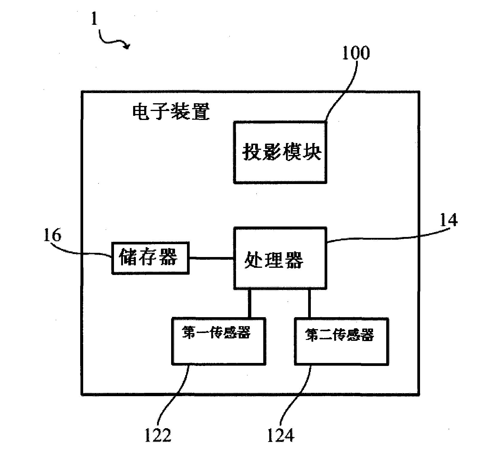
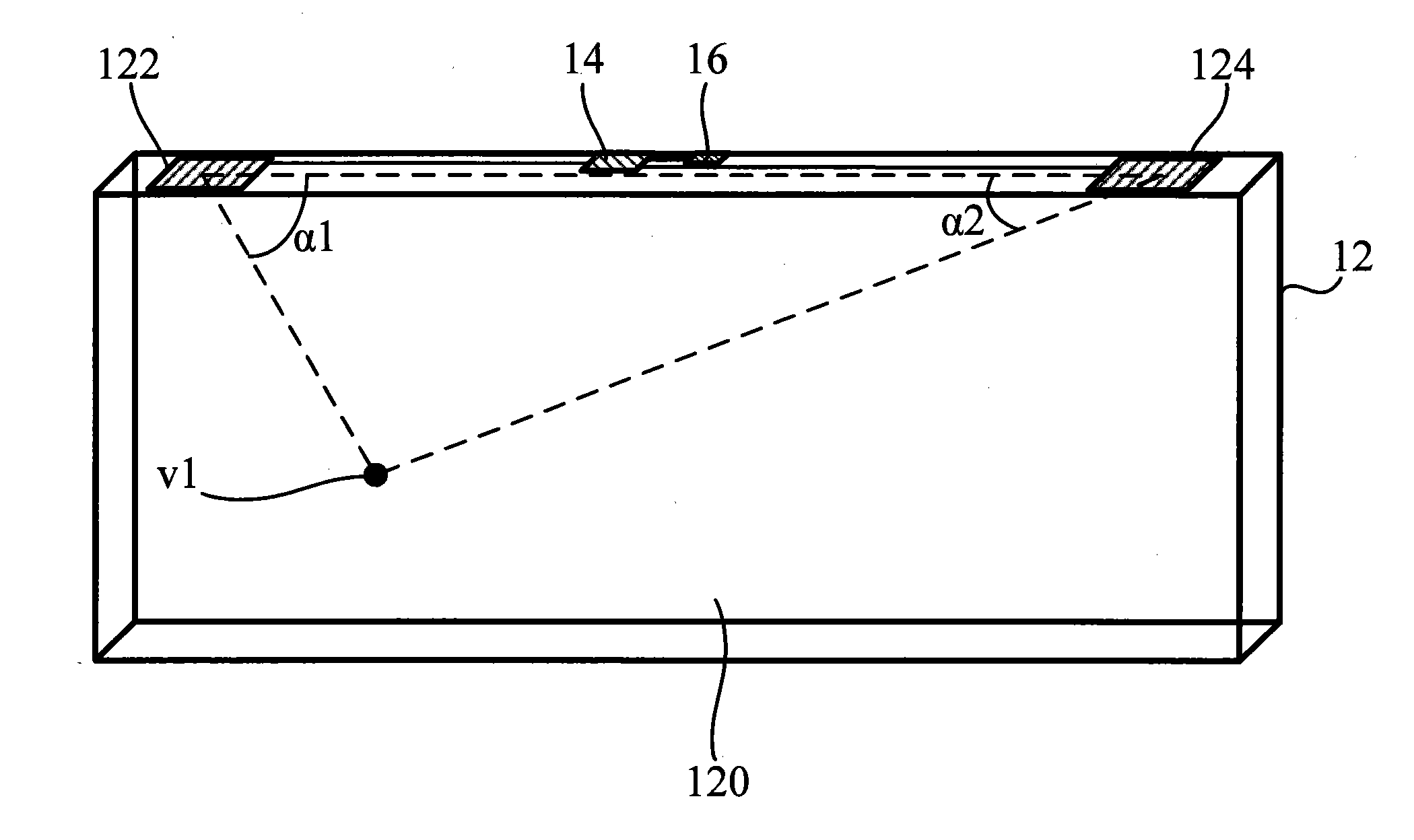
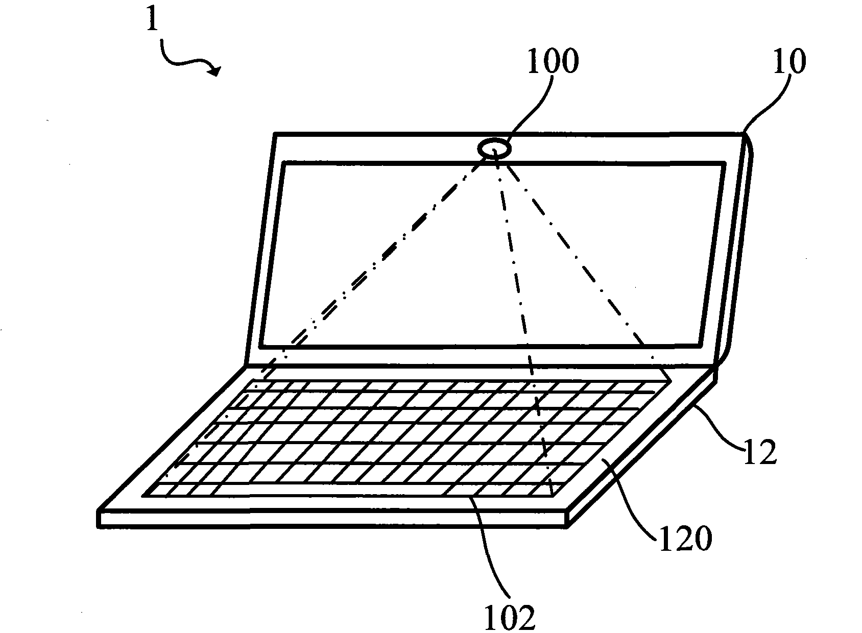
[0037] Please also see Figure 1A , Figure 1B , Figure 2A as well as Figure 2B , FIG. 1 is a block diagram of an electronic device according to a specific embodiment of the present invention; Figure 1B is a schematic diagram of a second body of an electronic device according to a specific embodiment of the present invention; Figure 2A It is a schematic diagram of opening the first body and the second body of the electronic device of the present invention; Figure 2B It is a schematic diagram of closing the first body and the second body of the electronic device of the present invention.

[0038] As shown in the figure, the electronic device 1 of the present invention includes a first body 10 , a second body 12 , a proces...


PUM


Abstract

The invention discloses an electronic device, which comprises a first body and a second body. The second body is pivoted on the first body and comprises a transparent base plate, a first sensor and a second sensor, wherein the transparent base plate is used for touching by the user; the first sensor is arranged on the transparent base plate and is used for sensing the touch of the user so as to output first sensing information; and the second body comprises a second sensor, a processor and a storage. By employing a vibration sensing technology for positioning the touch point of the user and touching the position coordinate to produce a command, the electronic device achieves the touch effect. Therefore, compared with the prior art, the electronic device can greatly reduce the components and has a touch function.

Description

technical field [0001] The present invention relates to an electronic device, in particular to an electronic device with a touch function. Background technique [0002] Common electronic devices are usually provided with operating modules such as keyboards, touch panels, and joysticks for users to input commands to the electronic devices. With the advancement of technology, touch screens have been developed and gradually widely used in electronic devices, allowing users to directly touch the screen to input commands, providing a more convenient input method. [0003] Current touch screens mainly include resistive touch screens and capacitive touch screens. Generally, a resistive touch screen uses glass as a transparent substrate, and a conductive layer and a resistive layer are covered on the glass panel. A spacer is used between the conductive layer and the resistive layer to allow current to flow between the two layers. Finally, a protective layer is covered on the cond...

Claims


Application Information

Patent Timeline
IPC IPC(8): G06F3/041G06F1/16
Inventor 黄智州
Owner INVENTECSHANGHAI TECH
Learn More