

Chip mounter
A placement machine, chip technology, applied in electrical components, semiconductor/solid-state device manufacturing, circuits, etc., can solve problems such as inability to suppress vibration, and achieve the effect of suppressing vibration
- Summary
- Abstract
- Description
- Claims
- Application Information
AI Technical Summary
Problems solved by technology
Method used
Image

Examples
Embodiment 1
[0030] based on Figure 1 to Figure 4 The first embodiment of the present invention will be described.
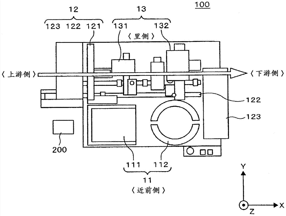
[0031] figure 1 It is a conceptual diagram seen from above of a die mounter according to an embodiment of the present invention. First, based on figure 1 A basic configuration example of a die mounter will be described. 100 is a die mounter, 11 is a wafer supply unit, 12 is a workpiece supply and transfer unit, 13 is a die mounter, and 200 is a control unit. As described above, the die mounter 100 includes the wafer supply unit 11, the workpiece supply and transfer unit 12, the die attach unit 13, and a control unit that controls these constituent devices (constituent devices including devices not shown). 200 constitutes.
[0032] In the wafer supply unit 11 , 111 is a cassette elevator, and 112 is a pickup device. In addition, in the workpiece supply and conveyance part 12, 121 is a stacker loader, 122 is a frame feeder, and 123 is an unloader. Moreover, in the die ...
Embodiment 2
[0054] The damper in Example 1 is a dynamic damper, and by effectively setting the intrinsic value of the damper, it is possible to cope with a wide range of vibration frequencies.
[0055] for Figure 4 The mounting head 403 of the vibration is set as ν 1 , set the mass to M B . Also, for the shock absorber 450, let the mass be M D , set the natural frequency of vibration to ν D , set the viscosity to C D . At this time, if γ=M D / M B ,but
[0056] ν D = ν 1 / (l+γ),
[0057] From this, the natural frequency of vibration ν is calculated D , viscous C D .
[0058] The above formula is based on "Research on Vibration Control Based on Air Attenuation Control Type Dynamic Damper" written by Kenichiro Tai, Minutes of Institute of Science and Technology, Meiji University, Volume 9, P109-141, 15-Jan-1973.
[0059] According to the above-mentioned embodiment, by effectively setting the intrinsic value of the shock absorber, a wide range of vibration frequencies can be...
Embodiment 3
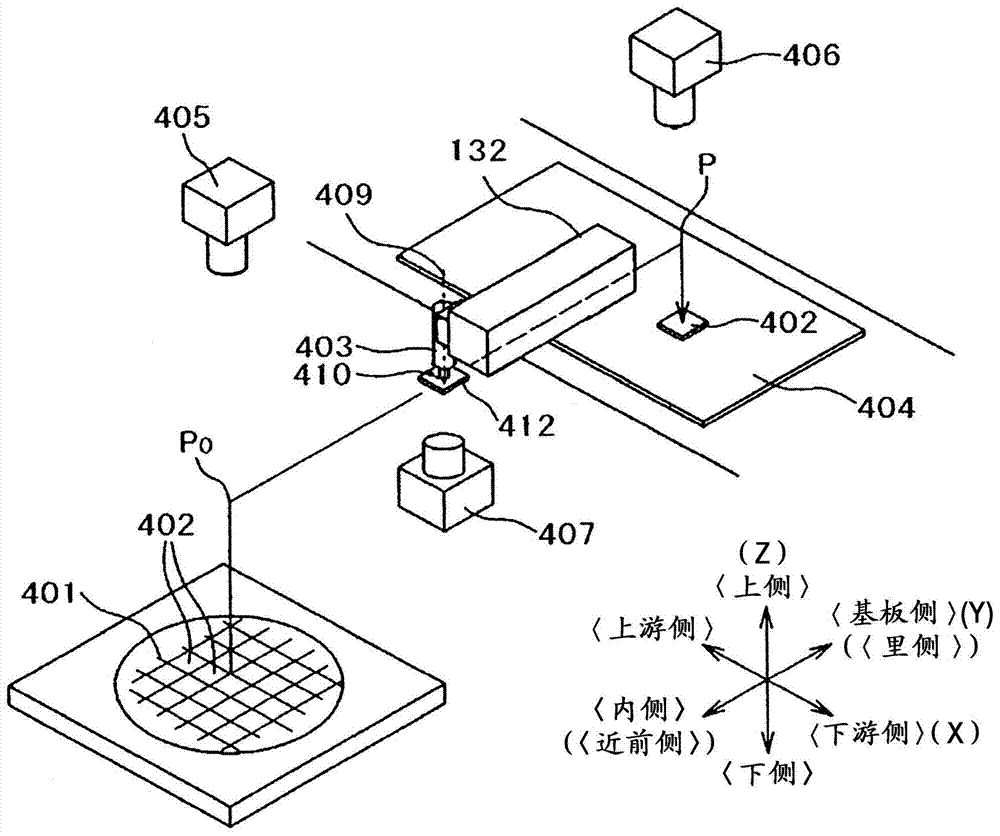
[0061] The shock absorbers in Example 1 and Example 2 are directed to the Y direction (near side-back side direction) where the vibration is large. But when image 3 Even in the X-direction (upstream-downstream direction) where there is no vibration, the placement head may generate vibration that is smaller than that in the Y-direction but affects accuracy. The damper 550 operates based on the vibration generated when the placement head 403 operates.
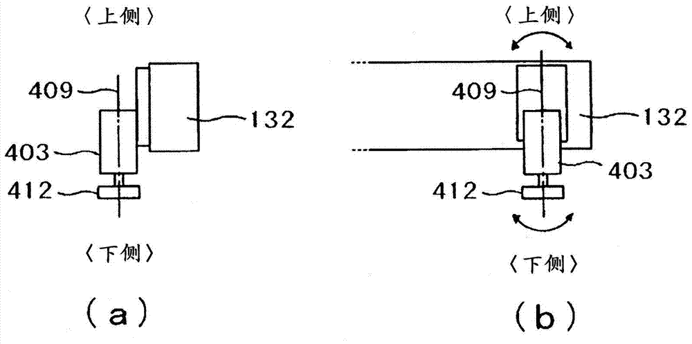
[0062] Thus, as shown in this embodiment Figure 5 shown, the settings are useful for Figure 4 The shock absorber 450 for suppressing the vibration in the Y-direction, and the shock absorber 550 for suppressing the vibration in the X-direction are also provided. In addition, in the case of using other methods to suppress vibration in the Y direction or when the vibration in the Y direction does not constitute an obstacle, etc., it is also possible to install a device that only suppresses the vibration in the X direction. F...
PUM
 Abstract
Description
Claims
Application Information