Supercharge Your Innovation With Domain-Expert AI Agents!

Multi-antenna terminal

A multi-antenna and terminal technology, applied in the directions of antenna, antenna coupling, antenna array, etc., can solve the problems of mutual interference of multiple antennas, mutual interference of antennas, etc., and achieve the effect of reducing the degree of signal mutual interference and effective signal isolation

Active Publication Date: 2015-03-25
ZTE CORP
View PDF2 Cites 4 Cited by
  • Summary
  • Abstract
  • Description
  • Claims
  • Application Information

AI Technical Summary

Problems solved by technology

This limits the distance between the antennas that cannot be placed ideally, thus, it is inevitable that multiple antennas will interfere with each other
The main reason for interference is that each antenna is connected to the common ground of the PCB board. When two adjacent antennas receive signals, a strong coupling current will be formed between the feeds of the two antennas, which leads to Mutual interference occurs between two adjacent antennas

Method used


Image

  • Multi-antenna terminal
  • Multi-antenna terminal

Examples


Embodiment Construction

[0018] It should be understood that the specific embodiments described here are only used to explain the present invention, not to limit the present invention.

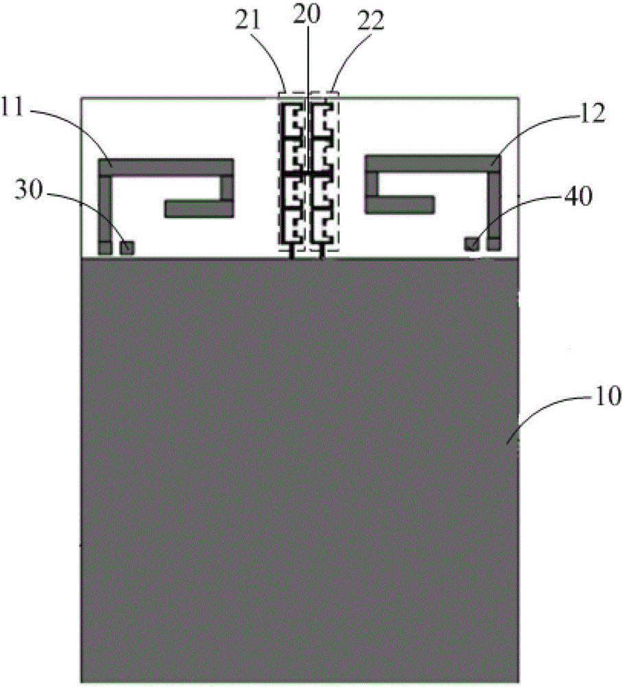
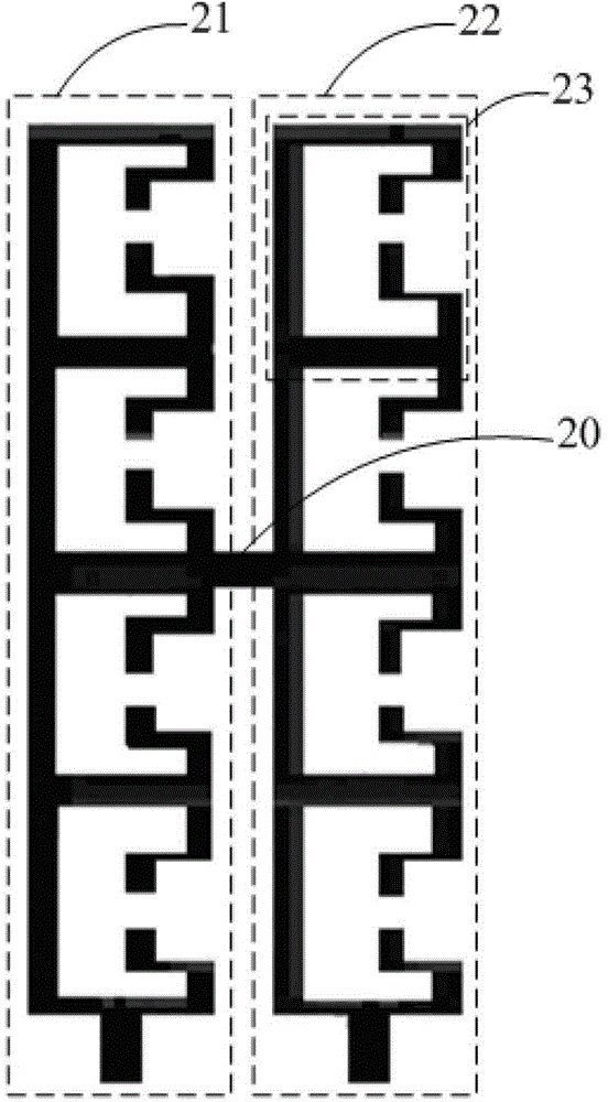
[0019] refer to figure 1 and figure 2 as shown, figure 1 is a schematic structural diagram of a preferred embodiment of a multi-antenna terminal in the present invention; figure 2 yes figure 1 Partial enlarged view in .

[0020] The multi-antenna terminal proposed in this embodiment includes a PCB board 10, a first antenna 11, a second antenna 12, an inductance element 20, a first split resonant ring group 21 and a second split resonant ring group 22, wherein: the first antenna 11 and The second antenna 12 is respectively connected to the ground wire on the PCB board 10; the first split resonant ring group 21 and the second split resonant ring group 22 are arranged between the first antenna 11 and the second antenna 12; The first split resonant ring group 21 and the second split resonant ring group 22 are arran...


PUM


Abstract

The invention discloses a multi-antenna terminal. The multi-antenna terminal comprises a PCB, a first antenna, a second antenna, an inductance element, a first opening resonance ring set and a second opening resonance ring set. The first antenna and the second antenna are connected with a grounding wire of the PCB, and the first opening resonance ring set and the second opening resonance ring set are arranged between the first antenna and the second antenna. The first opening resonance ring set and the second opening resonance ring set are arranged in parallel and connected with the grounding wire of the PCB. One end of the inductance element is connected with the first opening resonance ring set, and the other end of the inductance element is connected with the second opening resonance ring set. The problem of interference of signals between the antennas on a multi-antenna terminal in the prior art can be solved, and therefore a user can use the multi-antenna terminal more conveniently. The multi-antenna terminal has the advantages of being simple in structure, low in cost and the like.

Description

technical field [0001] The present invention relates to the technical field of multi-antenna terminals, in particular to a multi-antenna terminal. Background technique [0002] Multiple Input Multiple Output (MIMO) or Multiple Transmit Multiple Receive antenna technology is a major breakthrough in antenna technology in the field of wireless mobile communications. This technology can double the capacity and spectrum utilization of the communication system without increasing the bandwidth, and is a key technology that must be adopted by the new generation of mobile communication systems. MIMO technology allows multiple antennas to simultaneously transmit and receive multiple spatial streams (frequency bands) and is able to distinguish signals to or from different spatial orientations. The application of the multi-antenna system enables parallel data streams to be transmitted simultaneously. At the same time, using multiple antennas at the sending end or receiving end can sig...

Claims


Application Information

Patent Timeline
IPC IPC(8): H01Q1/52H01Q21/00
CPCH01Q1/243H01Q1/521H01Q9/42H01Q15/006H01Q1/523H01Q15/0086
Inventor 田超舒超凡刘洋
Owner ZTE CORP
Features
  • R&D
  • Intellectual Property
  • Life Sciences
  • Materials
  • Tech Scout
  • Unparalleled Data Quality
  • Higher Quality Content
  • 60% Fewer Hallucinations
Learn More