Low-pass filtering inverter system based on linear driving
What is Al technical title?
Al technical title is built by PatSnap Al team. It summarizes the technical point description of the patent document.
A linear drive, low-pass filtering technology, applied in the field of electronics, can solve the problems of increasing and damaging the polar capacitor of the power supply filter, and achieve the effect of improving the load capacity, simple structure and saving energy consumption.
Inactive Publication Date: 2015-03-25
CHENGDU SIMAO TECH
View PDF0 Cites 2 Cited by
Summary
Abstract
Description
Claims
Application Information
AI Technical Summary
This helps you quickly interpret patents by identifying the three key elements:
Problems solved by technology
Method used
Benefits of technology
Problems solved by technology
[0004] The purpose of the present invention is to overcome the problem that when the load of the current inverter is too large, the third harmonic component contained in the square wave current will increase the capacitive current flowing into the load, and in severe cases, it will damage the power filter pole of the load. To solve the defects of permanent capacitance, provide a low-pass filter inverter system based on linear drive
Method used
Image
Click on the blue label to locate the original text in one second.
Reading with bidirectional positioning of images and text.
Examples
Embodiment
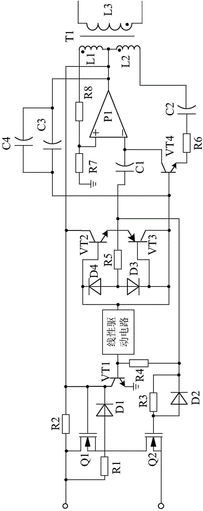
[0017] Such as figure 1 As shown, the low-pass filter inverter system based on linear drive of the present invention consists of a transformer T1, an inverter circuit, a linear drive circuit connected with the inverter circuit, a logic control circuit connected with the linear drive circuit, and a logic control circuit It is composed of connected low-pass filter circuits; the output end of the low-pass filter circuit is connected with the primary side of the transformer T1.
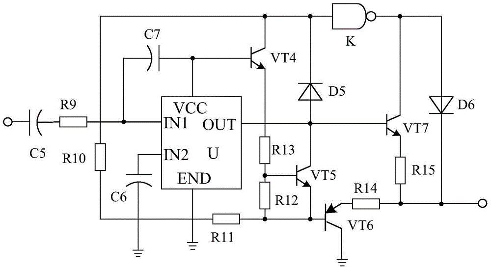
[0018] Such as figure 2 As shown, the linear drive circuit is composed of a drive chip U, a triode VT4, a triode VT5, a triode VT6, and a triode VT7. Sexual capacitor C5, one end is connected to the collector of the triode VT4, the other end is connected to the base of the triode VT6 after the resistor R11, the positive pole is connected to the base of the triode VT4, the negative pole is connected to the IN1 tube of the driver chip U Pin-connected polar capacitor C7, the positive pole is connected to ...
PUM
Abstract
The invention discloses a low-pass filtering inverter system based on linear driving. The system is characterized by being composed of a transformer T1, an inverter circuit, a linear driving circuit connected with the inverter circuit, a logic control circuit connected with the linear driving circuit and a low-pass filtering circuit connected with the logic control circuit; the output end of the low-pass filtering circuit is connected with the primary side of the transformer T1; the linear driving circuit is composed of a driving chip U, a triode VT4, a triode VT4, a triode VT6, a triode VT7, a polar capacitor C5, a resistor R10 and the like; the positive electrode of the polar capacitor C5 is connected with the inverter circuit, and the negative electrode of the polar capacitor C5 is connected with a pin IN1 of the driving chip U after passing through a resistor R9; one end of the resistor R10 is connected with the collector electrode of the triode VT4, and the other end of the resistor R10 is connected with the base electrode of the triode VT6 after passing through a resistor R11. Since the low-pass filtering inverter system based on linear driving is provided with the linear driving circuit, when the inverter system is used for driving large-load electric equipment, the electric equipment can be protected against damage by triple frequency harmonic.
Description
technical field [0001] The invention relates to the field of electronics, in particular to a low-pass filter inverter system based on linear drive. Background technique [0002] Inverters convert DC power into AC power. It is widely used in air conditioners, home theaters, electric grinding wheels, electric tools, sewing machines, DVD, VCD, computers, TVs, washing machines, range hoods, refrigerators, VCRs, massagers, fans, lighting, etc. In foreign countries, due to the high penetration rate of automobiles, the inverter can be used to connect the battery to drive electrical appliances and various tools to work when going out to work or travel. Connect household appliances to the output of the power converter to use various appliances in the car. [0003] However, when the inverter is used, because the load is too large, the third harmonic component contained in the square wave current will increase the capacitive current flowing into the load, and in severe cases, it will...
Claims
Application Information
Patent Timeline
Application Date:The date an application was filed.
Publication Date:The date a patent or application was officially published.
First Publication Date:The earliest publication date of a patent with the same application number.
Issue Date:Publication date of the patent grant document.
PCT Entry Date:The Entry date of PCT National Phase.
Estimated Expiry Date:The statutory expiry date of a patent right according to the Patent Law, and it is the longest term of protection that the patent right can achieve without the termination of the patent right due to other reasons(Term extension factor has been taken into account ).
Invalid Date:Actual expiry date is based on effective date or publication date of legal transaction data of invalid patent.