Eureka AIR delivers breakthrough ideas for toughest innovation challenges, trusted by R&D personnel around the world.

Wind energy plant with tilt adjustment system

一种风能设备、调节系统的技术,应用在机械设备、风能发电、风力发动机等方向,能够解决昂贵功率电子装置等问题,达到紧凑结构形式的效果

Inactive Publication Date: 2019-01-04
LIEBHERR COMPONENTS BIBERACH GMBH
View PDF5 Cites 0 Cited by
  • Summary
  • Abstract
  • Description
  • Claims
  • Application Information

AI Technical Summary

Problems solved by technology

[0009] Current electromechanical adjustment systems according to the prior art and the aforementioned electrohydraulic actuators require expensive power electronics
Among the available devices, compact solutions with all necessary functions such as normal operation, emergency tilting in case of power failure and mechanical locking in a safe position have not yet been realized

Method used


Image

  • Wind energy plant with tilt adjustment system
  • Wind energy plant with tilt adjustment system
  • Wind energy plant with tilt adjustment system

Examples


Embodiment Construction

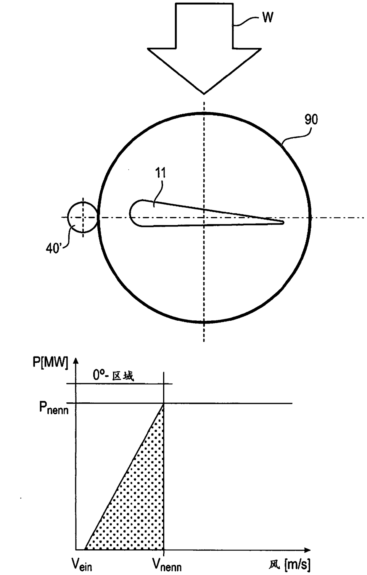
[0043] figure 1 A schematic diagram showing a rotor blade 11 or a rotor blade adjustment of a rotor blade 11 . exist figure 1 The rotor blades 11 are shown in what is referred to as the 0° zone, as this is contained in figure 1 obtained from the graph in . The rotor blades 11 can be adjusted by means of pitch adjustment means 40', which act on the blade bearings 90.

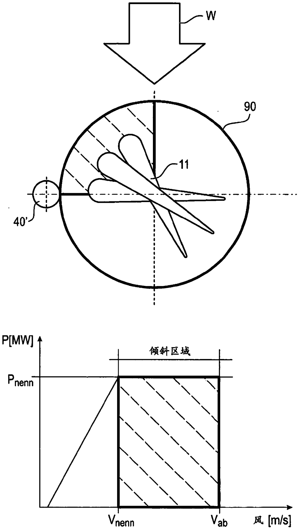
[0044] Therefore, such adjustments in the case of increased wind figure 2 shown in , where the so-called "sloped region" is not only in the figure 2In the diagram shown in the lower part of , and also in the schematic diagram of the rotor blade 11 , it is shown with dashed lines. the wind is figure 1 and figure 2 In , the wind is represented by the reference symbol W.

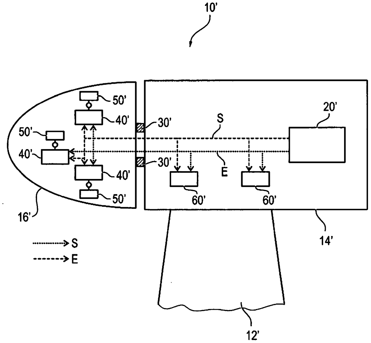
[0045] image 3 A known wind energy installation 10' with an electric pitch adjustment system 40' is shown. Here, the machine housing 14' of the wind energy installation 10' is mounted on the tower 12'. In the machine housing 14...


PUM


Abstract

The invention relates to a wind energy system with at least one pitch adjustment system for adjusting the pitch of at least one rotor blade of the wind energy system, wherein the pitch adjustment system comprises at least one electrohydraulic drive that comprises an unregulated electromotor rotating in one direction of rotation for generating pressure.

Description

technical field [0001] The invention relates to a wind energy installation with an inclination adjustment system for adjusting at least one rotor vane of a wind energy installation, and to an inclination adjustment system for a wind energy installation. Background technique [0002] The rotor blade adjustment of a wind turbine is also referred to as pitch adjustment system. The rotor blade adjustment in a wind energy installation (WEA) is used here to adjust the rotational speed of the rotor at increased wind speeds. If the so-called nominal wind speed is exceeded, the rotor blades are turned or pitched away from the wind via control logic. The maximum pivoting angle here is approximately 90°, which corresponds to the so-called dragging position. The drag position is used to bring the rotor to a standstill when the cut-off speed is reached. Wind energy installations are usually designed with three rotor blades, each rotor blade being equipped with a control system. Here ...

Claims


Application Information

Patent Timeline
Patent Type & Authority Patents(China)
IPC IPC(8): F15B15/26F03D7/02F15B13/08
CPCF03D7/0224F05B2210/11F05B2270/604F15B1/022F15B15/18F15B15/261F15B2015/268F15B2211/20515F15B2211/20576F15B2211/212F15B2211/3051F15B2211/411F15B2211/41554F15B2211/41563F15B2211/426F15B2211/7053F15B2211/7054F15B2211/8752Y02E10/72F03D80/88F03D9/25Y02E60/16F03D9/28
Inventor 安东·盖勒安东·施泰默尔奥利弗·文黑勒汉斯-彼得·拉韦涅
Owner LIEBHERR COMPONENTS BIBERACH GMBH
Why Eureka
Eureka Blog
Learn More