
Stapler

A technology of a stapler and a stand base, which is applied in the directions of manufacturing tools, staple staple tools, etc., can solve the problems of inconvenient staples, the inability to achieve the best labor-saving effect, and the long resistance arm of the upper cover.

Active Publication Date: 2015-04-01
DELI GROUP CO LTD
View PDF7 Cites 7 Cited by
  • Summary
  • Abstract
  • Description
  • Claims
  • Application Information

AI Technical Summary

Problems solved by technology

[0002] The patent with the publication number CN102335903A discloses a labor-saving stapler, which adds an auxiliary upper cover and realizes labor-saving operation with the principle of double levers, but because the lower end of the auxiliary upper cover is hinged at the front end of the base, the upper end of the auxiliary upper cover The first transmission pin is slidingly connected in the first chute of the upper cover, so that the lower end of the auxiliary upper cover cannot move, and the second transmission pin on the nail pressing plate is located near the front end of the nail pressing plate. , so that the upper end of the auxiliary upper cover and the first chute are closer to the middle position of the upper cover, so that when the upper cover is pressed down, the resistance arm of the upper cover is longer, so that the labor-saving effect cannot be optimal, and the upper cover can be opened The angle is small, making it less convenient to put staples into the nail channel

Method used


Image

  • Stapler
  • Stapler
  • Stapler

Examples


Embodiment Construction

[0016] The present invention will be described in further detail below in conjunction with the accompanying drawings and specific embodiments.

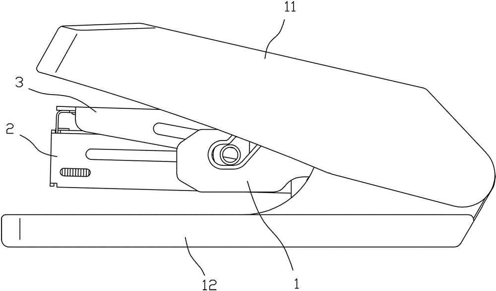
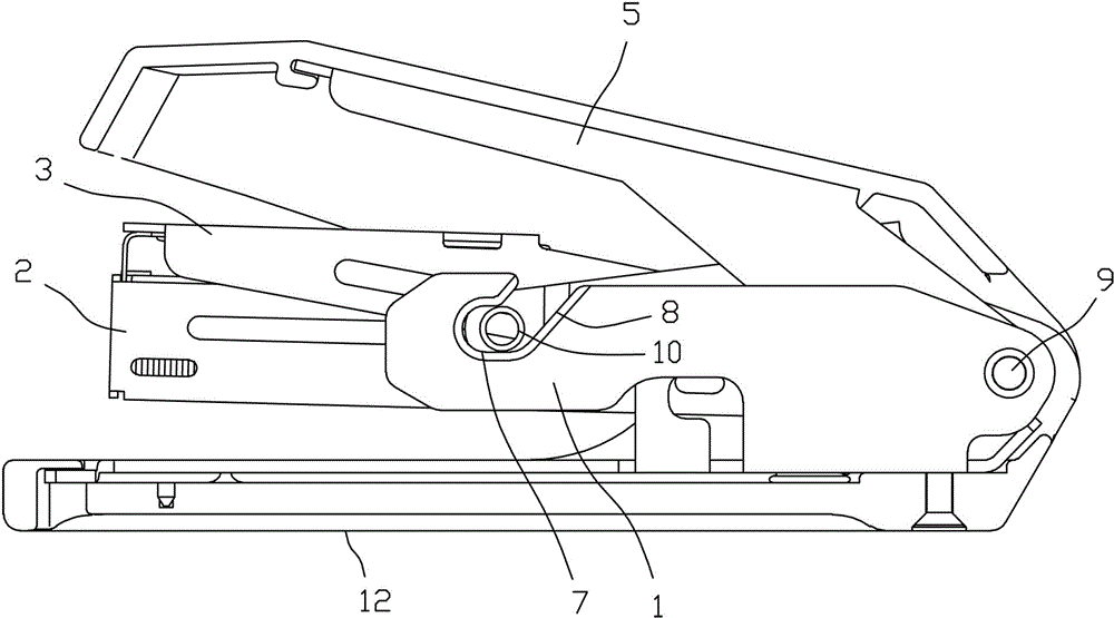
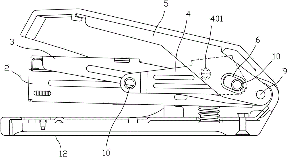
[0017] Depend on Figure 1~Figure 5 As shown, the stapler of the present invention comprises a support seat 1, a nail track 2, an upper blade assembly 3, a hinge 4 and a loam cake 5, and the tail ends of the nail track 2, the upper blade assembly 3 and the loam cake 5 are all Hinged to the tail end of the bracket base 1, so that the nail channel 2, the upper blade assembly 3 and the upper cover 5 can rotate relative to the bracket base 1, the side wall of the upper cover 5 is provided with a first guide, and one end of the hinge 4 Slidingly connected on the first guide part, the first guide part is arranged as a structure that can make one end of the hinge 4 move to the rear end of the upper cover 5 and press down when the upper cover 5 is pressed down.

[0018] As a preferred solution, the first guide part is a first chute 6, and th...


PUM


Abstract

The invention discloses a stapler, comprising a bracket, a nail path, an upper blade assembly, a hinge and an upper cover, wherein the tail ends of the nail path, the upper blade assembly and the upper cover are hinged on the tail end of a bracket seat, a first guide part is arranged on the side wall of the upper cover, one end of the hinge is connected to the first guide part in a sliding manner, the first guide part is set to of a structure that one end of the hinge is moved towards the tail end of the upper cover and is pressed downwards when the upper cover is pressed downwards, a second guide part is arranged on the side wall of the bracket seat, the other end of the hinge is connected to the second guide part in a sliding manner, the second guide part is set to of a structure that the other end of the hinge is moved towards the front end of the bracket seat when the upper cover is pressed downwards and the other end of the hinge is deviated from the bracket seat when the upper cover is opened, the middle position of the hinge is hinged with the middle position of the upper blade assembly, and the first guide part is close to the tail end of the upper cover. The stapler disclosed by the invention has a good labor saving effect and stitching needles can be arranged conveniently.

Description

technical field [0001] The invention relates to a stapler. Background technique [0002] The patent with the publication number CN102335903A discloses a labor-saving stapler, which adds an auxiliary upper cover and realizes labor-saving operation with the principle of double levers, but because the lower end of the auxiliary upper cover is hinged at the front end of the base, the upper end of the auxiliary upper cover The first transmission pin is slidingly connected in the first chute of the upper cover, so that the lower end of the auxiliary upper cover cannot move, and the second transmission pin on the nail pressing plate is located near the front end of the nail pressing plate. , so that the upper end of the auxiliary upper cover and the first chute are closer to the middle position of the upper cover, so that when the upper cover is pressed down, the resistance arm of the upper cover is longer, so that the labor-saving effect cannot be optimal, and the upper cover can ...

Claims


Application Information

Patent Timeline
Patent Type & Authority Applications(China)
IPC IPC(8): B25C5/02B25C5/11
CPCB25C5/00B25C5/11B25C5/025B25C5/1617
Inventor 俞杰辉
Owner DELI GROUP CO LTD
Learn More