Supercharge Your Innovation With Domain-Expert AI Agents!

Yarn oiling device

A yarn and oil tank technology, applied in textiles and papermaking, can solve the problems of oil waste and oil overflow

Inactive Publication Date: 2015-04-01
XINCHANG COUNTY RONGTAI DEV
View PDF0 Cites 1 Cited by
  • Summary
  • Abstract
  • Description
  • Claims
  • Application Information

AI Technical Summary

Problems solved by technology

However, the existing yarn oiling and lubricating devices generally can only oil one filament, and are no longer suitable for production devices that produce multiple filaments at the same time.
Moreover, there is also a device for oiling and lubricating the yarn. The yarn generally passes through the oiling groove in parallel, and the oil is easy to overflow from the through hole through which the yarn passes, resulting in a waste of oil.

Method used


Image

  • Yarn oiling device

Examples


Embodiment Construction

[0011] Below in conjunction with accompanying drawing, the present invention will be further described:

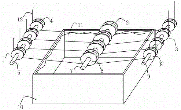
[0012] Such as figure 1 As shown, the structure diagram of the yarn oiling and lubricating device of the present invention is given, which includes a front wire-feeding wheel set 1, a lower pressing wheel set 2, a rear wire-feeding wheel set 3 and an upper oil groove 10, and the upper oil groove 10 is located at the bottom The oil 11 for oiling the yarn 12 is stored under the pressure wheel set 2 and in the oiling tank 10 . The front wire wheel set 1 shown is composed of a front wheel shaft 5 and four front wire wheels 4, and the front wire wheels 4 are rotatably arranged on the front wheel shaft 5 to realize the guiding effect on the yarn 12. The lower pressure wheel group 2 is composed of a middle wheel shaft 7 and a plurality of middle wire wheels 6, the middle wire wheel 6 is rotatably fixed on the middle wheel shaft 7, and the lower half of the middle wheel shaft 7 i...


PUM


Abstract

The invention relates to a yarn oiling device. The yarn oiling device is characterized in that a front yarn guide wheel set is composed of a front wheel shaft and a plurality of front yarn wheels arranged on the front wheel shaft, a rear yarn guide wheel set is composed of a rear wheel shaft and a plurality of rear yarn wheels rotatably arranged on the rear wheel shaft, and a lower roller set is composed of a middle wheel shaft and a plurality of middle yarn wheels rotatably fixed on the middle wheel shaft; oil for lubricating yarns is stored in an oiling tank, the lower roller set is located above the oiling tank and the lower part of the middle yarn wheel is immersed into the oil; yarns are orderly wound around the front yarn wheel, the middle yarn wheel and the rear yarn wheel. According to the yarn oiling device, the oiling tank for storing the oil is arranged under the lower roller set to realize simultaneous oiling and lubricating on a plurality of yarns, and therefore, the oiling requirement of the production line for simultaneously producing a plurality of yarns is met. The lower roller set is arranged to be lower than the front yarn guide wheel set and the rear yarn guide wheel set, and therefore, the form that the yarns must be put through the oiling tank in the past is avoided and the defect of easy outflow of the oil is solved.

Description

technical field [0001] The invention relates to a yarn oiling device. Background technique [0002] In the yarn production process, in order to ensure the quality of the finished yarn, it needs to be oiled and lubricated. However, the existing yarn oiling and lubricating devices generally can only oil one filament, and are no longer suitable for production devices that produce multiple filaments at the same time. Moreover, there is also a device for oiling and lubricating the yarn. The yarn generally passes through the oiling groove in parallel, and the oil easily overflows from the through hole through which the yarn passes, resulting in a waste of oil. Contents of the invention [0003] In view of the problems existing in the prior art, the object of the present invention is to provide a technical solution for a yarn oiling device. [0004] The above-mentioned yarn oiling device includes a front wire-feeding wheel set, a lower pressure wheel set, a rear wire-feeding wh...

Claims


Application Information

Patent Timeline
Patent Type & Authority Applications(China)
IPC IPC(8): D01H13/30
CPCD01H13/306
Inventor 王春苗
Owner XINCHANG COUNTY RONGTAI DEV
Features
  • R&D
  • Intellectual Property
  • Life Sciences
  • Materials
  • Tech Scout
  • Unparalleled Data Quality
  • Higher Quality Content
  • 60% Fewer Hallucinations
Learn More