Automatic oil coating device for large flange

A technology for oiling devices and large flanges, which is applied in spraying devices, wind power generation, etc., can solve problems such as not being able to meet the oiling needs of large flanges, and achieve the effects of stable and reliable transmission structure, convenient oiling, and high efficiency

Pending Publication Date: 2022-07-12
山东重诺锻造股份有限公司
View PDF0 Cites 0 Cited by
  • Summary
  • Abstract
  • Description
  • Claims
  • Application Information

AI Technical Summary

Problems solved by technology

[0003] The present invention provides an automatic oiling device for large flanges to solve the problem that the above existing equipment cannot meet the oiling requirements of large flanges

Method used


Image

  • Automatic oil coating device for large flange
  • Automatic oil coating device for large flange
  • Automatic oil coating device for large flange

Examples


Embodiment 1

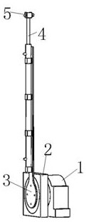
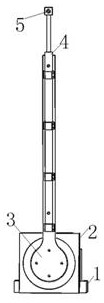
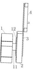
[0037] Attached below Figure 1-9 The present invention is further described as attached figure 1 and 2 The large flange automatic oiling device shown includes a driving device 1, a slewing bearing device 2, a rotating plate 3, a linear telescopic device 4 and an anti-rust oil atomizing nozzle 5.

[0038] like Image 6 As shown, the slewing ring device 2 includes a slewing ring bearing 22 and a bearing seat 21, the outer ring of the slewing ring bearing 22 is mounted on the bearing seat 21, and the bearing seat 21 is fixed on the mounting platform.

[0039] like figure 1 and 3 As shown, the drive device 1 is drivingly connected to the inner ring of the slewing support bearing 22; one end of the rotating plate 3 in the length direction is fixedly or detachably connected to the inner ring of the slewing support bearing 22 away from the drive device 1 side.

[0040] like figure 1 and 2 As shown, the linear telescopic device 4 is installed on the rotating plate 3 , and the ...

Embodiment 2

[0053] The difference between this embodiment and Embodiment 1 is: Figure 9 As shown, in this embodiment, the large flange automatic oiling device is installed on the mobile lifting platform, and the large flange can be oiled at the flange use site.

[0054] The working principle of the large-scale flange automatic oiling device of the present invention:

[0055] The installation platform of the large flange automatic oiling device is a fixed platform (Example 1) or a mobile lifting platform (Example 2). During use, by adjusting the large flange or mobile lifting platform, the slewing bearing device 2 and the large flange can be adjusted. Then adjust the extension length of the movable end of the linear expansion device 4 so that the movable end of the linear expansion device 4 can reach the annular area of ​​the large flange; , so that the spraying range of the anti-rust oil atomizing nozzle 5 coincides with the width of the annular area of ​​the large flange, or is smaller...


PUM


Abstract

The invention belongs to the technical field of flange oiling, and particularly relates to a large flange automatic oiling device which comprises a driving device, a slewing bearing device, a rotating plate, a linear telescopic device and an anti-rust oil atomizing nozzle. Compared with the prior art, the automatic oiling device for the large flange has the advantages that the driving device (1) is started to drive the inner ring of the slewing bearing and the rotating plate to rotate, and the anti-rust oil atomizing nozzle is used for oiling the annular area of the flange in the rotating process until surface oiling is completed; the oil coating of the large flange is very convenient, and the efficiency is high; (2) the extension length of the movable end of the linear telescopic device is adjusted, so that the movable end of the linear telescopic device can reach the annular area of the large flange; the automatic oil coating device for the large flange can meet the oil coating requirements of flanges with different diameters; and (3) the mounting disc of the driving device, the inner ring of the slewing bearing and the rotating plate connecting part are connected through bolts, and the transmission structure is stable and reliable.

Description

technical field [0001] The invention belongs to the technical field of flange oiling, and in particular relates to a large flange automatic oiling device. Background technique [0002] Large flanges refer to flanges that exceed the dimensions specified by the relevant state departments. Generally refers to the flange size above DN2000. Flange anti-corrosion treatment mainly adopts anti-corrosion measures such as oiling and galvanizing. The diameter of large flanges is very large, and the existing equipment cannot meet the oiling needs of large flanges. SUMMARY OF THE INVENTION [0003] The present invention provides an automatic oiling device for large flanges in view of the problem that the above-mentioned existing equipment cannot meet the oiling needs of large flanges. [0004] In order to achieve the above purpose, the technical scheme adopted in the present invention is as follows: the large flange automatic oiling device includes a driving device, a slewing bearing...

Claims


Application Information

Patent Timeline
Patent Type & Authority Applications(China)
IPC IPC(8): B05B13/04B05B15/628
CPCB05B13/0426B05B15/628Y02E10/72
Inventor 张林
Owner 山东重诺锻造股份有限公司
Why Eureka
Try Eureka