
Floating device for power head of trenchless pipe laying rig

A drilling rig power head and floating device technology, which is applied in the direction of rotary drilling rigs, earthwork drilling, drilling equipment, etc., can solve the problems affecting the use of the power head floating device and the fracture of the connecting shaft, and achieves ingenious structure, water sealing, and design reasonable effect

Active Publication Date: 2016-08-17
无锡市钻通工程机械有限公司
View PDF7 Cites 0 Cited by
  • Summary
  • Abstract
  • Description
  • Claims
  • Application Information

AI Technical Summary

Problems solved by technology

When the horizontal directional drilling power head cooperates with the floating device of the power head for construction, the floating nipple needs to be able to float back and forth with the position of the drill pipe when loading and unloading the drill pipe. Swing, especially when hard objects or obstacles are suddenly encountered during construction, the situation is more severe, and the connecting shaft in the floating device of the power head is prone to break due to the swing of the floating nipple, which affects the use of the floating device of the power head

Method used


Image

  • Floating device for power head of trenchless pipe laying rig

Examples


Embodiment Construction

[0010] The present invention will be further described below in conjunction with specific drawings and embodiments.

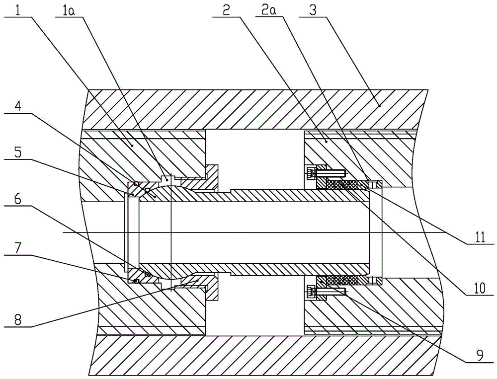
[0011] As shown in the figure: the floating device of the power head of the non-excavation pipelaying drilling rig in the embodiment is mainly composed of the main shaft of the power head 1, the floating nipple 2, the spline sleeve 3, the spherical water shaft 4, the wear ring 5, the first O Type sealing ring 6, the second O-ring 7, gland 8, baffle 9, water seal 10 and liner 11.

[0012] Such as figure 1 As shown, the main shaft 1 of the power head and the floating sub-joint 2 are connected through the spline sleeve 3. Since the floating sub-joint 2 can move axially in the spline sleeve 3 as required, the floating sub-joint 2 and the spline sleeve 3 adopt clearance fit; the inner hole of the main shaft 1 of the power head and the inner hole of the floating nipple 2 are sealed and connected by a hollow spherical water shaft 4; the first end of the spherical wa...


PUM


Abstract

The invention relates to a floating device for a power head of a non-excavation pipelaying drilling rig, which includes a main shaft of the power head, a floating sub-joint and a spline sleeve. The gap fit is adopted between the sleeves; it is characterized in that: the inner hole of the main shaft of the power head and the inner hole of the floating nipple are sealed and connected by a hollow spherical water shaft; the first end of the spherical water shaft is set as a spherical surface , the first end is connected to the main shaft of the power head through the first sealing connection assembly; the second end of the spherical water shaft is set as a cylindrical surface, and the second end is connected to the floating nipple through the second sealing connection assembly. The invention has ingenious structure and reasonable design. When the cylindrical surface at the second end of the spherical water shaft is subjected to an external load, the spherical surface at the first end of the spherical water shaft can rotate freely to balance the forces on both ends. Ensure the water seal of the entire spherical water shaft.

Description

technical field [0001] The invention relates to a floating device for a power head of a non-excavation pipe-laying drilling rig, which belongs to the technology of non-excavation pipe-laying machinery. Background technique [0002] At present, the horizontal directional drilling power head can use the power head floating device to optimize the power head floating and protect the large gear of the power head. The key component of the floating device of the power head is the hollow connection shaft connecting the main shaft of the power head and the floating nipple. A reasonable structure of the connecting shaft is the prerequisite to ensure the reliable operation of the floating device of the power head. When the horizontal directional drilling power head cooperates with the floating device of the power head for construction, the floating nipple needs to be able to float back and forth with the position of the drill pipe when loading and unloading the drill pipe. Swing, esp...

Claims


Application Information

Patent Timeline
Patent Type & Authority Patents(China)
IPC IPC(8): E21B3/02E21B7/04
CPCE21B3/02E21B7/046
Inventor 徐松于峰贾绍宽牛民
Owner 无锡市钻通工程机械有限公司
Learn More