Manufacturing method of transformer bobbin based on lead frame

A technology of a transformer skeleton and a manufacturing method, which is applied in the field of transformers, can solve the problems of reducing production efficiency, increasing labor cost, and small winding space for a wire binding portion, and achieves the effects of improving production efficiency and ensuring coplanarity.

Active Publication Date: 2016-09-21
MORNSUN GUANGZHOU SCI & TECH
View PDF5 Cites 0 Cited by
  • Summary
  • Abstract
  • Description
  • Claims
  • Application Information

AI Technical Summary

Problems solved by technology

Since the pin 50 is integrally composed of the wire binding part and the patch part, the winding space of the wire binding part is small, and the distance between adjacent pins is compact, the wire diameter and the number of wire strands that can be wound for each pin there is a big limit
If there are too many strands of enameled wire, a large section will be formed at the wire binding position after being bound to the terminal, which will lead to tin connection between adjacent terminals after tinning, and will affect the overall pin coplanarity of the transformer
In actual production, because of the process and quality problems of wire binding, this kind of transformer can only rely on manual work in most cases, and special control is carried out on the terminal wire binding and tin immersion of the transformer after winding, which seriously reduces the production efficiency. , adding extra man-hour cost

Method used


Image

  • Manufacturing method of transformer bobbin based on lead frame
  • Manufacturing method of transformer bobbin based on lead frame
  • Manufacturing method of transformer bobbin based on lead frame

Examples


no. 1 example

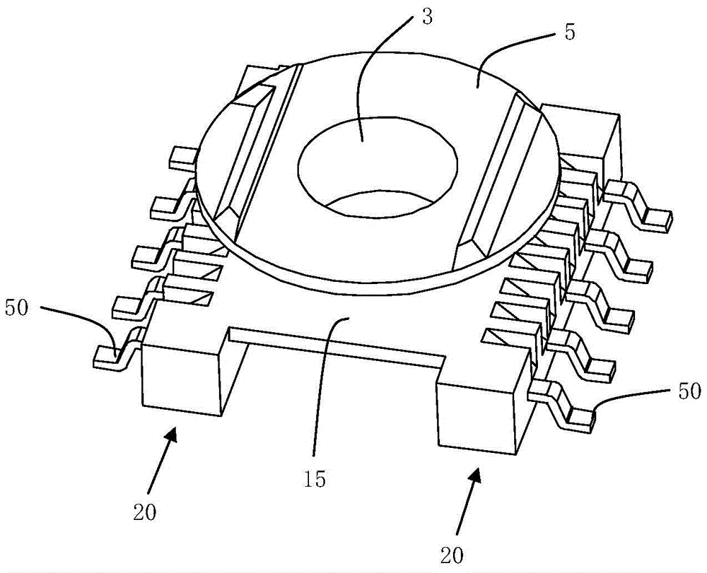
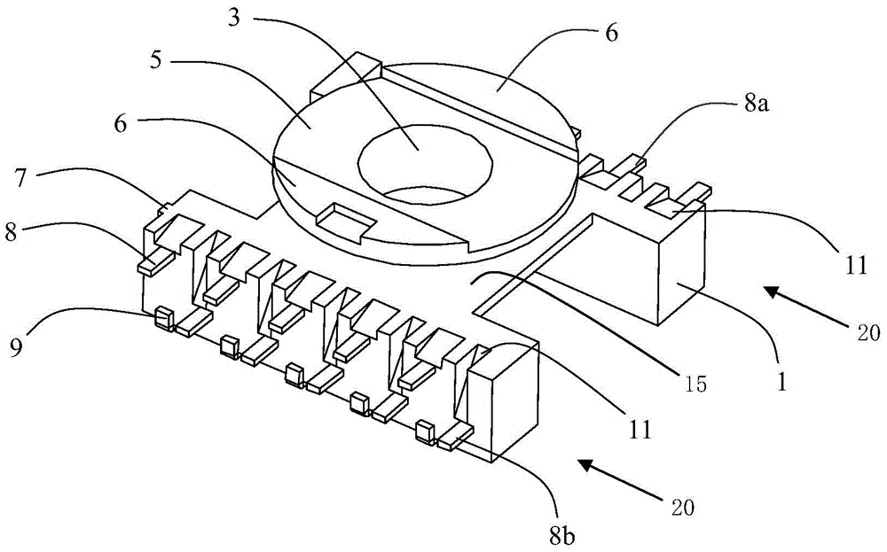
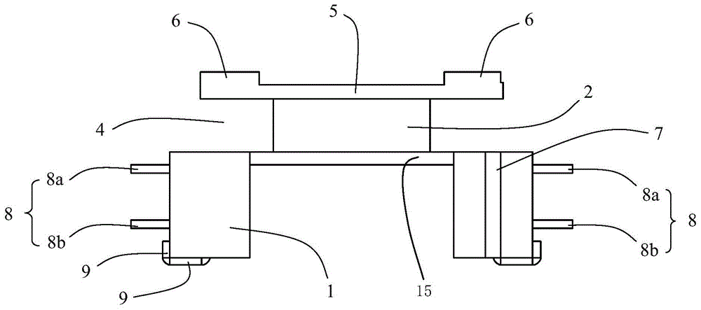
[0055] Figure 2-1 to Figure 2-4 It is a structural diagram of the transformer skeleton of the first embodiment of the present invention, diagram 2-1 is a perspective view of the transformer skeleton of the first embodiment of the present invention, Figure 2-2 It is the front view of the transformer skeleton of the first embodiment of the present invention, Figure 2-3 It is a top view of the transformer skeleton in the first embodiment of the present invention, Figure 2-4 It is a side view of the transformer skeleton in the first embodiment of the present invention. It includes coil bobbin 1, winding post 2, magnetic core assembly hole 3, winding package limit slot 4, transformer winding package block 5, magnetic core assembly limit strip 6, pin position identification point 7, wire binding guide Pin 8, patch pin 9, connecting arm 10, lead groove 11.

[0056] The winding post 2 is located on the coil bobbin 1, and a magnetic core assembly hole 3 is provided inside the ...

no. 2 example

[0061] Figure 5-1 to Figure 5-4 It is a structural diagram of the transformer skeleton of the second embodiment of the present invention, Figure 5-1 is a perspective view of the transformer skeleton of the second embodiment of the present invention, Figure 5-2 It is the front view of the transformer skeleton of the second embodiment of the present invention, Figure 5-3 It is a top view of the transformer skeleton of the second embodiment of the present invention, Figure 5-4 It is a side view of the transformer skeleton of the second embodiment of the present invention. The difference from the first embodiment of the present invention lies in the structure and quantity of the binding pins 8 and patch pins 9 , as well as the number of lead slots 11 , and other structures are the same as the first embodiment.

[0062] There are two straight wire-binding pins in each group of wire-binding pins 8 in the first embodiment, and here there is only one straight wire-binding pin....


PUM


Abstract

The invention provides a wire leading frame of a novel ER flat bobbin, which can well solve the problems of wire winding of the winding terminal of a transformer, tin immersion, tin connection and poor coplanarity and realizes full-automatic wire winding. The wire leading frame consists of a plurality of wire leading units which are connected with metal frames, each wire leading unit consists of a slim rectangular patch pin section, a connecting arm, and a first wire winding pin section, the patch pin sections are connected with the metal frames, the other ends of the patch pin sections are perpendicularly connected with the connecting arms, the other ends of the connecting arms are perpendicularly connected with the first wire winding pin sections, the other ends of the first wire winding pin sections are suspended in the air and point to the directions which are opposite to the patch pin sections, and the wire-leading unit structure in which the patch pin sections and the first wire winding pin sections are mutually staggered in the horizontal direction and the vertical direction is formed.

Description

technical field [0001] The invention relates to a transformer, in particular to a lead frame of a flat transformer skeleton capable of automatic winding for making a high power density DC / DC power converter, a manufacturing method of the transformer skeleton based on the lead frame, and the transformer skeleton. Background technique [0002] With the continuous development of switching power supply technology, the size of the module power supply is getting smaller and smaller, but the corresponding power density is getting higher and higher, and the miniaturization of power devices such as transformers is imperative. The current DC-DC medium and high-power module power supplies usually use planar transformers with high overall cost; while small and micro-power module power supplies still prefer traditional skeleton transformers with low cost. For low-voltage input and low-voltage output DC / DC low-power module power supplies with large operating current and high operating fre...

Claims


Application Information

Patent Timeline
Patent Type & Authority Patents(China)
IPC IPC(8): H01F27/29H01F27/30H01F41/04H01F41/10
Inventor 向宇峰蔡家添
Owner MORNSUN GUANGZHOU SCI & TECH
Why Eureka
Try Eureka