Method and system for mobile phone antenna coupling test on production line

A mobile phone antenna and test system technology, which is applied to antenna radiation patterns, transmitter monitoring, electromagnetic field characteristics, etc., can solve the problems of increased test labor costs, difficult standardization of procedures, and long time consumption, and improves test accuracy and test efficiency. , improve efficiency and accuracy, and improve the effect of test efficiency

Active Publication Date: 2015-04-08
上海鑫测信息技术有限公司
View PDF5 Cites 20 Cited by
  • Summary
  • Abstract
  • Description
  • Claims
  • Application Information

AI Technical Summary

Problems solved by technology

[0003] 1. Traditional coupling test system is inefficient and takes more and more time
Due to the continuous increase of standards and frequency bands, the traditional system adopts a serial test method, which makes the coupling of a single mobile phone more and more time-consuming, and the increase in the cost of coupling testing has become a major factor in the increase in the testing cost of mobile phone factories.
[0004] 2. The traditional coupling test system cannot meet the increasingly high quality requirements of the product. This problem has a relatively large relationship with the near-field environment of the current coupling test system flat-panel antenna and the interference of the USB cable.
[0005] 3. The traditional coupling test system cannot complete the antenna coupling test of all standards in one station
At present, there are more and more standards and frequency bands supported by mobile phones, and the antenna needs to be designed more and more complex. The most obvious feature is the use of multiple antennas to meet the needs of multiple standards and frequency bands. For example, the main set of all systems consists of two antennas. Realization, the diversity of some standards is realized by one antenna, and the WIFI is realized by one antenna. The antenna configuration of such a mobile phone is 4 antennas, and each antenna may be distributed in different positions of the fuselage. The traditional way of shielding box + flat-panel antenna It is impossible to find an accurate location suitable for testing all antennas in a shielding box, that is, one station cannot complete the coupling of all antennas; the solution adopted by the industry to solve this problem is basically to divide the coupling, resulting in many types of coupling stations, and the stations cannot be standardized , the number of operators required is also increasing, the cost of testing labor increases, and the process is difficult to standardize

Method used


Image

  • Method and system for mobile phone antenna coupling test on production line
  • Method and system for mobile phone antenna coupling test on production line
  • Method and system for mobile phone antenna coupling test on production line

Examples


Embodiment 1

[0061] The invention discloses a mobile phone antenna coupling test system on a production line. The system includes: a coupling test module (software subsystem), an industrial computer, a multi-signal source device, a radio frequency cable, a combiner, and a coupling shielding box.

[0062] The coupling test module is the software subsystem of the present invention, and the industrial computer, multi-signal source device, radio frequency cable, combiner, and coupling shielding box constitute the hardware subsystem of the present invention.

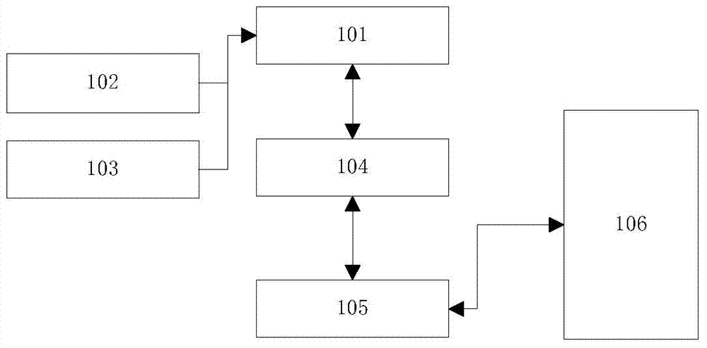
[0063] figure 1 Represents the system diagram of the system software sub-module MOS, 101 represents the UI module, and the mobile phone antenna couples the human-computer interaction, process and result display interface; 102 represents the graphics library module, providing various graphics management libraries for realizing 101; 103 is the font library, providing 101 The fonts required by the module; 104 represents the coupling test pro...

Embodiment 2

[0082] The difference between this embodiment and Embodiment 1 is that this embodiment discloses a mobile phone antenna coupling test system, which includes: a coupling test module, an industrial computer, a multi-signal source device, a radio frequency cable, a combiner, a coupling shielding box.

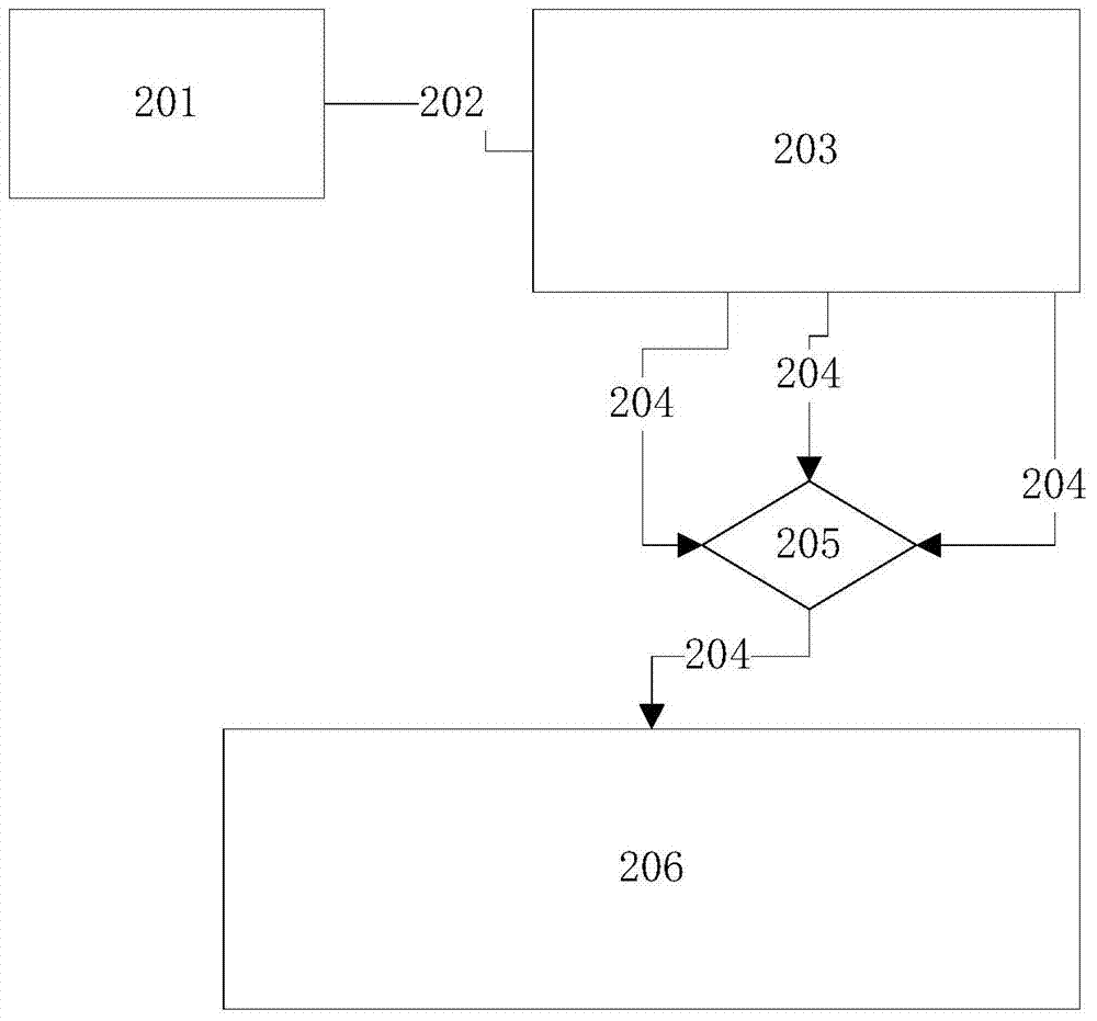
[0083] The coupling test module is a built-in test software of the mobile phone, which is used to set the coupling test of the mobile phone to be tested; the entire coupling test process is built into the mobile phone, and the physical layer of the mobile phone is directly controlled by the coupling test module to perform various basic operations and tests of radio frequency Action, test the radio frequency performance of the mobile phone antenna, and directly display the test data and test results through the mobile phone display. Coupling test module includes user interface UI unit, graphics library unit, font library unit, coupling test processing unit, drive library unit, inter...


PUM


Abstract

The invention discloses a method and a system for mobile phone antenna coupling test on a production line. The system comprises a coupling test module, an industrial personal computer, a multi-signal-source device, radio-frequency cables, a combiner and a coupling shielding box. The coupling test module comprises mobile internal test software for coupling test of a to-be-tested mobile phone in set process; the industrial personal computer is connected with the multi-signal-source device and used for configuration of parameters of the multi-signal-source device and controlling a transmission channel of the multi-signal-source device to open or close; the multi-signal-source device under control of the industrial personal computer is used for generating radio-frequency signals with multiple frequency points for mobile phone antenna coupling; the radio-frequency cable is arranged between the multi-signal-source device and the combiner and between the combiner and the coupling shielding box respectively; the coupling shielding box is used for placement of at least one mobile phone and used for broadcast type parallel coupling test of mobile phones. The method and the system for mobile phone antenna coupling test on a production line have the advantage that test efficiency and precision can be improved.

Description

technical field [0001] The invention relates to the field of antenna coupling testing of a whole machine on a mobile phone production line, in particular to a system and method for a plurality of whole machine broadcasting parallel coupling tests in a shielding box. Background technique [0002] At present, mobile phones are becoming more and more complicated. The antenna coupling test of the whole production line mainly uses the traditional shielding box and the hardware system of the flat-panel antenna. The coupling program on the industrial computer side controls the mobile phone to perform non-signaling transmission and communication through the USB (Universal Serial Bus) data line. Coupling tests for receiving metrics. The traditional non-signaling coupling system of the whole production line antenna has become increasingly obvious in the following three issues: [0003] 1. Traditional coupling test system is inefficient and takes more and more time. Due to the contin...

Claims


Application Information

Patent Timeline
Patent Type & Authority Applications(China)
IPC IPC(8): H04B17/12G01R29/08G01R29/10
Inventor 张晓胡斌刘家杰华斌臣
Owner 上海鑫测信息技术有限公司
Why Eureka
Try Eureka