Candle wick holder and method of making the same

A technology of holding parts and candle wicks, which is applied in the directions of candle wicks, burning methods, candle preparation devices, etc., can solve the problems of expensive candle wick holding parts and the like

Inactive Publication Date: 2017-09-12
STC GMBH
View PDF3 Cites 0 Cited by
  • Summary
  • Abstract
  • Description
  • Claims
  • Application Information

AI Technical Summary

Problems solved by technology

This has the disadvantage that additional expensive tools are required for the production of the different wick holders
As a result, the manufacture of wick holders, especially in small batches, is expensive

Method used


Image

  • Candle wick holder and method of making the same
  • Candle wick holder and method of making the same
  • Candle wick holder and method of making the same

Examples


Embodiment Construction

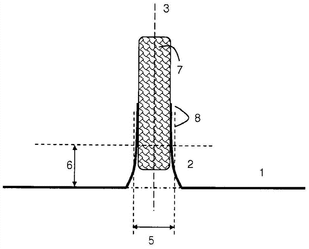
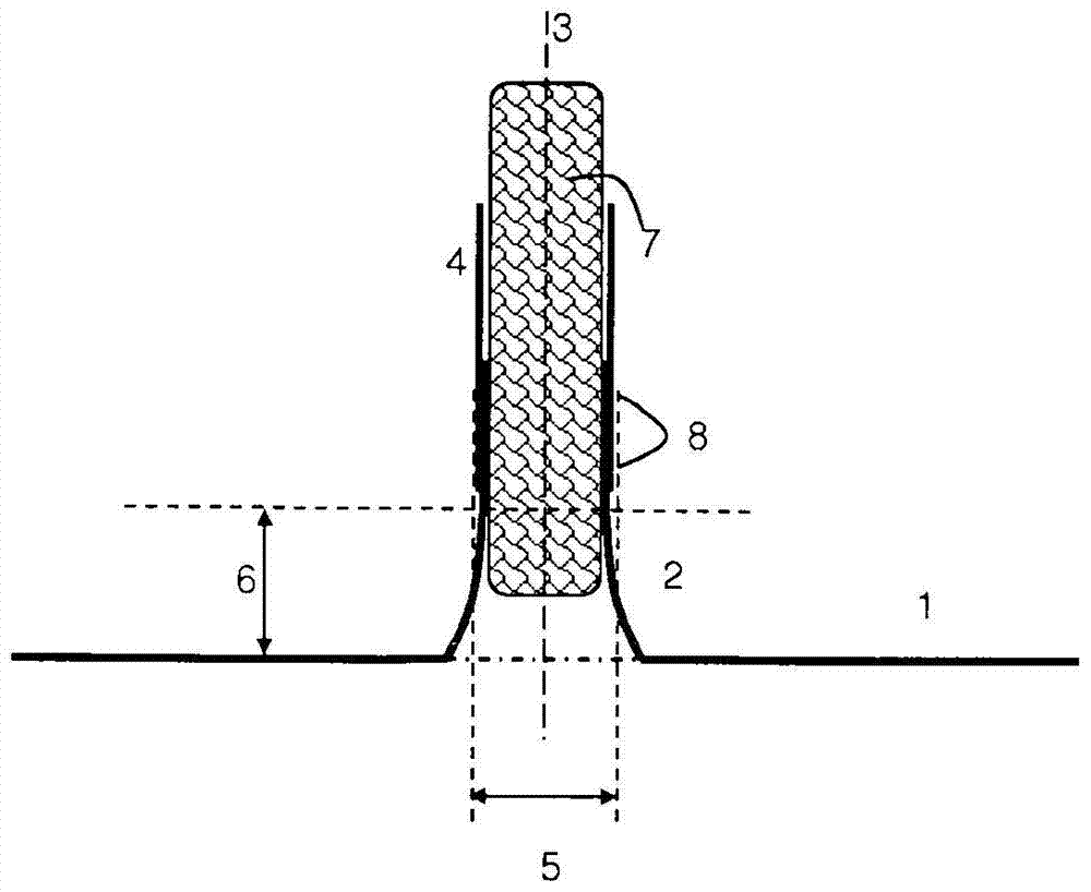
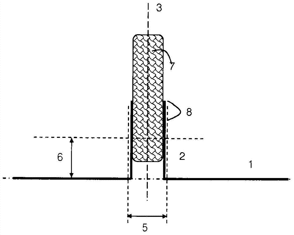
[0049] According to the invention, a wick holder is provided which comprises a base plate 1 with a central channel in the form of a hollow cylindrical projection 2 (neck). The cylinder axis 3 of the hollow cylindrical protrusion is perpendicular to the base plate 1 . Known wick holders also have these features of the wick holder according to the invention, which are used as a starting point for the production of the wick holder according to the invention. Unlike known wick holders ( figure 1 , 3 and 5), in the wick holder by the present invention ( figure 2 , 4 In and 6), the hollow cylindrical extension 4 (extension piece) is installed on the hollow cylindrical protrusion 2, so that the cylinder axis 3 of the hollow cylindrical protrusion and the hollow cylindrical extension coincide.

[0050] In addition to the supporting function of the neck 2 , the candle wick 7 is also supported by this extension 4 . Furthermore, if the wick 7 burns to the upper edge of the extensio...


PUM


Abstract

The invention relates to a candle wick holder comprising a base plate (1) with a central channel in the form of a hollow cylindrical protrusion (2) whose cylinder axis (3) is perpendicular to the base plate. A cylindrical extension (4) is arranged on the hollow cylindrical protrusion such that the hollow cylindrical protrusion coincides with the axis (3) of the hollow cylindrical extension.

Description

technical field [0001] The invention relates to a wick holder for a candle, comprising a base plate with a hollow neck as a passage for the wick, and to a method of manufacturing the wick holder. Background technique [0002] Wick holders are primarily used in tea candles. For making tea candles, it is preferred to use paraffin wax or to use a mixture of natural waxes with stearin or other suitable fuels. The fuel is cold-pressed into a suitable shape, for example in pellet form, or cast in liquid form into the tea candle holder. Simpler tea candles are pressed without a wick. The candle body is then drilled and the wick is guided through the hole in the wick holder. Thus, the wick holder basically serves to keep the wick straight in the wax. [0003] Typical known wick holders are stamped parts, which are produced in different sizes, preferably from cold-rolled sheet steel or aluminum sheet, preferably by means of so-called progressive dies. In the stamping die, the sh...

Claims


Application Information

Patent Timeline
Patent Type & Authority Patents(China)
IPC IPC(8): C11C5/00
CPCC11C5/006Y10T29/49348C11C5/02F21V35/003F23D3/16F23D3/24
Inventor J·克雷默M·克雷默
Owner STC GMBH
Why Eureka
Try Eureka