Spinal plate assembly

a technology of spinal cord and bone plate, which is applied in the field of spinal cord plate assembly, can solve the problems of design detriment, bone screw retraction, and bone screw retraction, and achieve the effect of reducing the strength of the bone plate, and reducing the risk of fractur

Inactive Publication Date: 2007-12-13
PAUL KAMALJIT S
View PDF99 Cites 0 Cited by
  • Summary
  • Abstract
  • Description
  • Claims
  • Application Information

AI Technical Summary

Benefits of technology

[0008] It is an object of the invention to provide spinal plate assemblies which facilitate secure bone-to-bone fixation and / or support, such as at e.g. adjacent or second adjacent vertebrae, while accommodating post-procedural compression between the respective bones.
[0042] In a fourth family of embodiments, the invention comprehends a spinal plate assembly. The spinal plate assembly comprises a spinal plate, the spinal plate comprising a top surface, a bottom surface opposite the top surface, the bottom surface being adapted to be positioned adjacent bone structure of a recipient user, and a plurality of bone-fastener-receiving apertures adapted to receive bone fasteners therethrough for mounting the spinal plate assembly to the bone structure of the recipient user, the spinal plate further comprising a length and a width, and a thickness between the top surface and the bottom surface, channel structure extending alongside respective ones of the apertures and generally aligned with the top surface of the spinal plate, the channel structure comprising at least one channel having a collective length, a bottom, and first and second sides, at least one of the first and second sides of the at least one channel having an opening therein extending into a respective bone-fastener-receiving aperture; and blocking structure in respective ones of the at least one channel, the blocking structure in a given channel having a length, and comprising at least a first band having a length, and extending along a side of the channel, the at least one band being resiliently urged into engagement with the side of the channel. The band extends across the opening in the respective side of the channel, and thus extends into the respective aperture, the band being effective, as a consequence of driving a bone fastener through the respective aperture, to respond to a side force applied by an interfering element of the bone fastener by moving transversely of the length of the respective band, and away from the interfering element, and by returning to a blocking position over the interfering element after the interfering element passes the band, whereafter the position of the band over the interfering element is effective to inhibit withdrawal of the bone fastener, past the band, and out of the spinal plate assembly.

Problems solved by technology

A common problem associated with the use of such spinal plates is the tendency of the bone screws to “back-out” or pull away or otherwise withdraw from the bone into which they are mounted.
This problem occurs primarily due to the normal torsional and bending motions of the body and spine.
This is a particularly important problem because as the screws become loose and pull away or withdraw from the bone, the heads of the screws can rise above the surface of the spinal plate and, possibly, even work their way completely out of the bone.
While this condition can cause extreme discomfort for the recipient user of the spinal plate, this condition can also create a number of potentially serious physiological problems given the significant amount of nervous and vascular structures located at or near the potential locations of anterior spinal plate fixations.
All of these designs have detriments, which include potential for breakage of the screws, or which require particular precision and alignment in their application in order to work correctly.
Additionally, loose components and accessories of spinal plates, which address the “backing-out” or withdrawal problem, can get dropped and / or misplaced while the vertebral fixation surgical procedure is taking place, prolonging and complicating the procedure as well as creating substantial risk of harm to the recipient.
Yet another common problem associated with the use of such spinal plates is the tendency, of the vertebrae which are being treated to settle after the spinal plate has been installed.
Such settling adds compression forces to the above-listed forces, and raises the probability that the bone screws will break, will back out, or pull away, or otherwise withdraw, from the bone to which they were mounted.

Method used


Image

  • Spinal plate assembly
  • Spinal plate assembly
  • Spinal plate assembly

Examples


Embodiment Construction

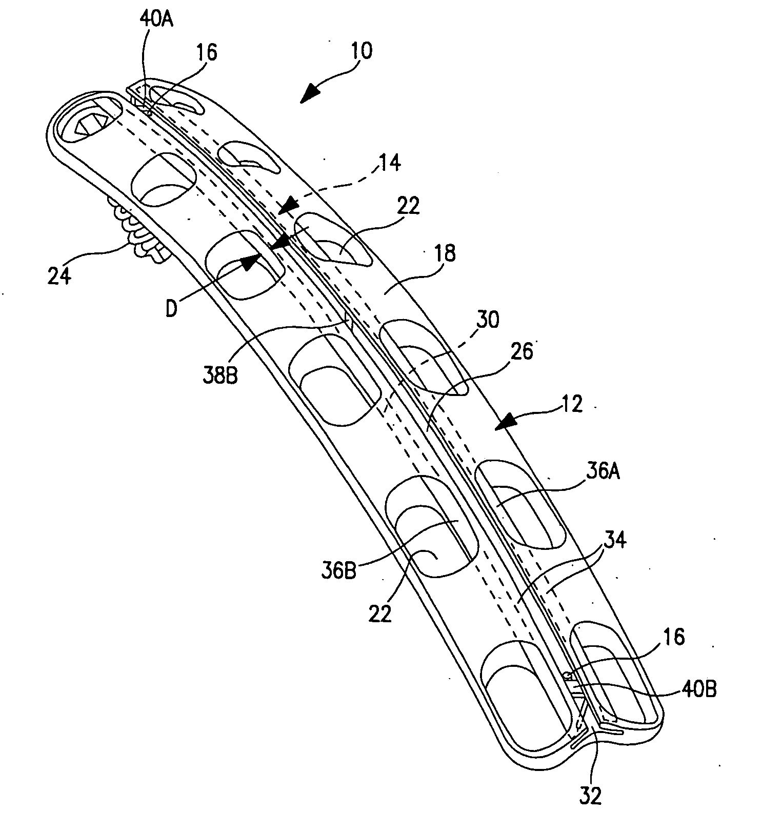
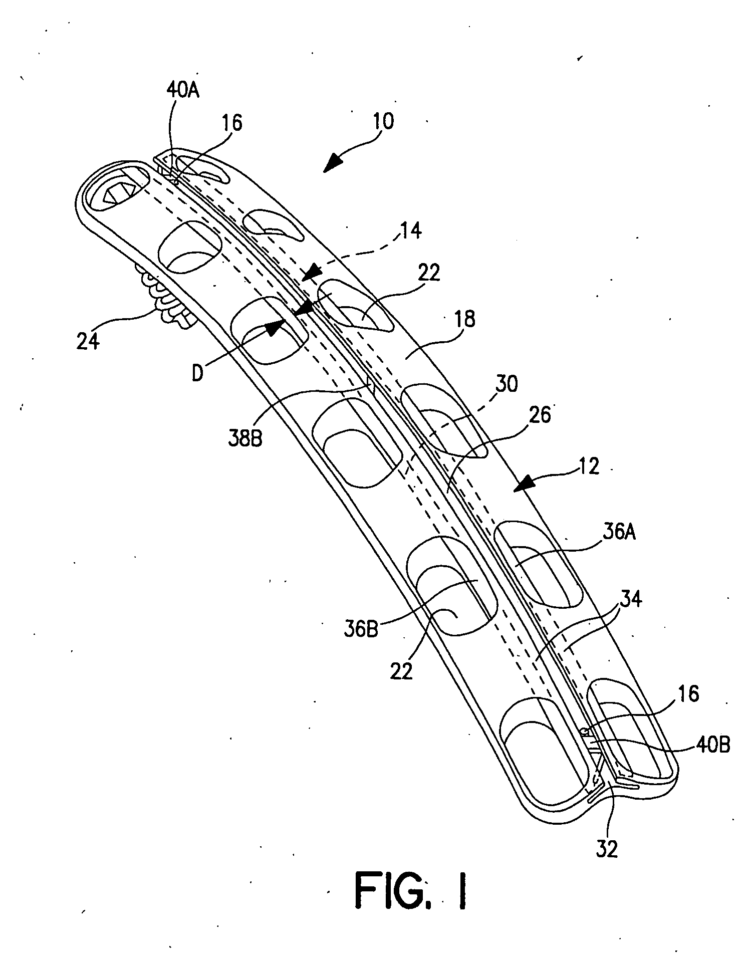
[0059] Referring now to the embodiments represented by FIGS. 1-5, a spinal plate assembly 10 of the invention includes a spinal plate 12, a blocking structure generally represented by 14 in FIG. 1, and one or more retaining structures 16.

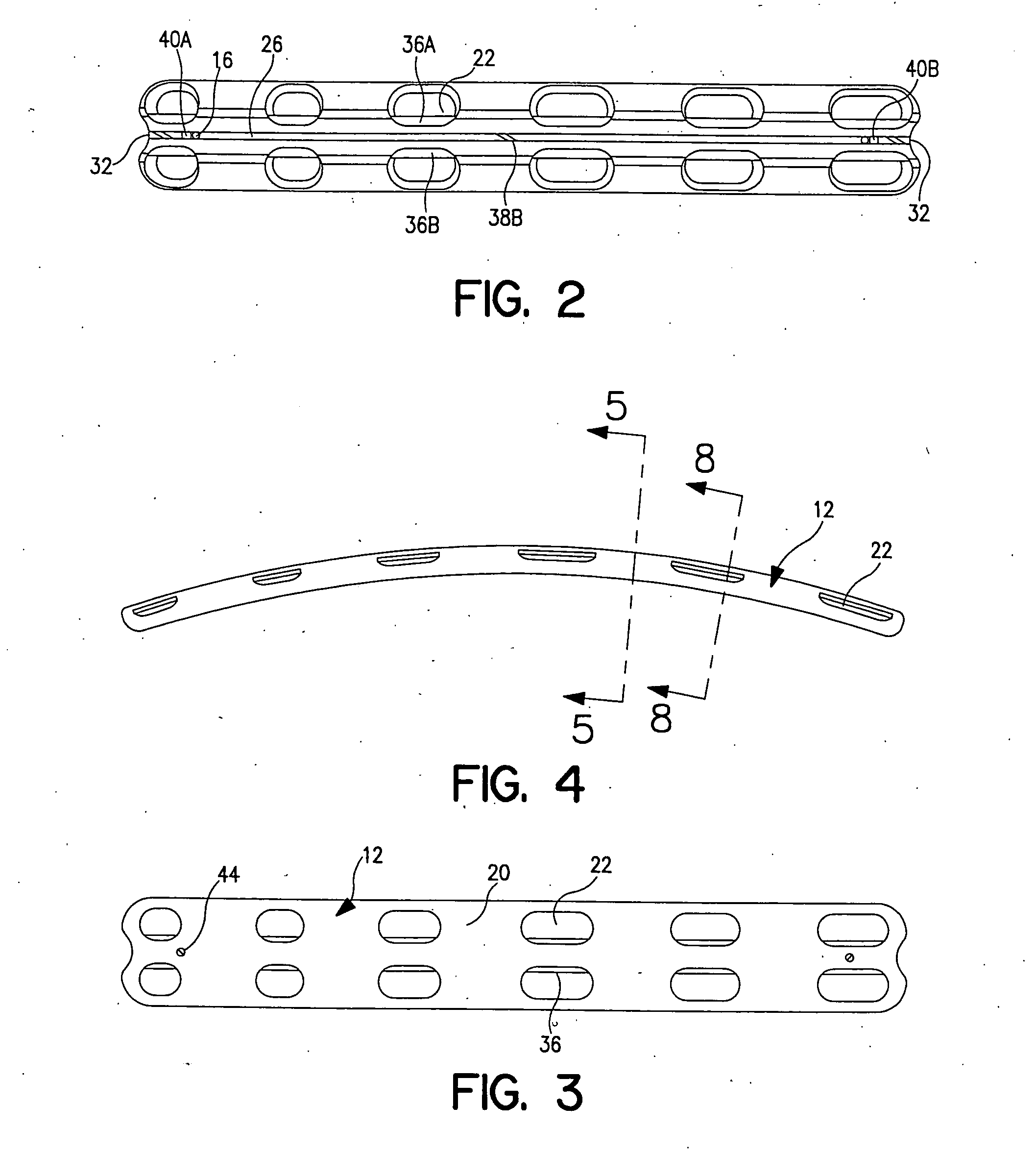
[0060] Spinal plate 12 has a top surface 18, a bottom surface 20 adapted to be positioned adjacent bone structure of a recipient user of the spinal plate assembly, and a plurality of bone-fastener-receiving apertures 22 which receive bone fasteners such as bone screws 24. Apertures 22 are arranged in first and second rows of such apertures, along the length of the spinal plate.

[0061] Top surface 18 of the spinal plate defines a channel 26 extending along the length of the spinal plate. Channel 26 has a bottom wall 28, opposing side walls 30, and has openings 32 extending out the respective ends of spinal plate 12, best illustrated in FIG. 5. An opening 32 is also illustrated in FIG. 1. Channel 26 further has overhanging top walls 34 extending inwa...


PUM


Abstract

Spinal plate assemblies, methods of fabrication, and methods of use. Such assemblies comprises blocking structures assembled to spinal plates. The blocking structure comprises an elongate band which can be against structure of the plate. The band is mounted into a continuous or intermittent channel in the plate, and extends into an aperture in the plate. The band responds to side forces applied by interfering elements of bone fasteners driven through an aperture, by moving away from the interfering element, and returning to a blocking position over the interfering element after the interfering element has passed the band. Methods of fabrication include inserting the blocking structure, optionally longitudinally, into the channel. Methods of use include advancing bone screws through an aperture and past the band. The bone screw deflects the band as the screw passes, and the band moves to the blocking position when the screw has moved past the band.

Description

[0001] The present invention relates to devices for the fixation and / or support of bones. In particular, the present invention relates to a spinal plate assembly, and a corresponding spinal plate, for the fixation and / or support of bones of the spinal column. The plate of the present invention has particular application in situations where compressional or settling forces, as well as torsional and flexing forces, of “fixed” vertebrae on a spinal plate cause significant stressing and potential failure of the spinal plate and / or plate components. [0002] Vertebral fixation has become a common approach to treating spinal disorders and fractures, and for fusion of vertebrae at the time such fixation is instituted. [0003] Namely, one or more vertebrae are fixed in position relative to one or more other vertebrae above and / or below the vertebrae to be fixed. Generally, a spinal plate is the device of choice used for mechanically supporting such vertebral fixation. A typical spinal plate in...

Claims


Application Information

Patent Timeline
Patent Type & Authority Applications(United States)
IPC IPC(8): A61B17/56A61B17/28A61B17/70A61B17/80A61B17/86A61B17/88
CPCA61B17/2812A61B17/282A61B17/7059A61B17/8047Y10S606/911A61B2017/8655Y10S606/907Y10S606/902A61B17/8869
Inventor PAUL, KAMALJIT S.
Owner PAUL KAMALJIT S
Why Eureka
Try Eureka