
Actuator consisting of two magnetic bearing motors

A bearing motor, magnetic bearing technology, applied in the direction of bearings, shafts and bearings, electric components, etc.

Inactive Publication Date: 2017-11-17
WHYLOT SAS CALFATECH
View PDF2 Cites 0 Cited by
  • Summary
  • Abstract
  • Description
  • Claims
  • Application Information

AI Technical Summary

Problems solved by technology

This document does not describe any bearing motors, but only radial magnetic bearings, and this rotating machine has the same drawbacks as previously mentioned

Method used


Image

  • Actuator consisting of two magnetic bearing motors
  • Actuator consisting of two magnetic bearing motors
  • Actuator consisting of two magnetic bearing motors

Examples


Embodiment Construction

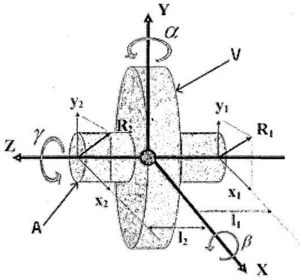
[0043] figure 1 Shown is a rotating element V, which can be a flywheel, and its shaft A. This figure refers to the rotation to show the possible degrees of freedom of the element V.

[0044] Assuming that this rotating element V is completely free, its motion in space can be described by a combination of three translations and three rotations relative to an orthogonal reference frame in terms of The axis Z of the extension of the axis of the rotating shaft member A, the axis Y contained in the plane of said element V and the axis X perpendicular to the first axis Z and the second axis Y are shown.

[0045] The three rotational degrees of freedom are rotation α around axis Y, rotation β around axis X, and rotation γ around axis Z. In the case that the flywheel V is intended to rotate about the axis Z, only the rotation γ is free, the rest are considered as parasitic rotations.

[0046] Still assuming that element V is completely free, there are three translational degrees of...


PUM


Abstract

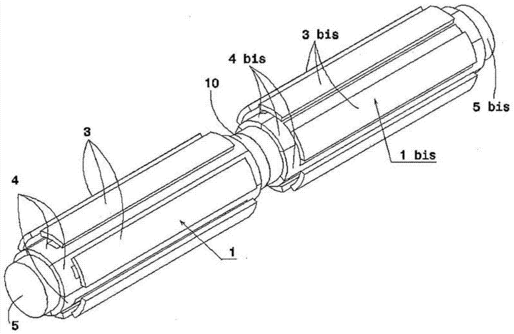
The invention relates to an actuator comprising at least two magnetic bearing motors. Said actuator is characterized in that said actuator comprises two magnetic bearing motors (1, 1bis) extending one from the other, said two bearing motors (1, 1bis) being angularly offset relative to each other. The actuator is also characterized in that an active or passive bearing (13) is inserted between said two bearing motors (1, 1bis), said bearing (13) being in each bearing motor (1, 1bis) at said The rotor part (3, 3bis) and the stator part (4, 4bis) act, and the housing (10) is arranged on the actuator between the first bearing motor (1) and the second bearing motor (1bis) to receive the bearing (13). The invention is suitable for use in the field of motors.

Description

technical field [0001] The invention relates to an actuator comprising two magnetic bearing motors. Background technique [0002] Traditional electric motors or generators require bearings to support and guide the rotation of the drive shaft. The majority of mechanical elements used in existing applications are ball or sleeve bearings. Their operating limits are still reached quickly in applications with high speeds of rotation, with specific environments or in vacuum, at very low or very high temperatures, or in areas where friction and wear have to be reduced as much as possible. [0003] In that case, it is already known to use magnetic bearings for electric motors or generators, those magnetic bearings not being subject to friction-induced wear. Such magnetic bearings ensure that there is no contact between the stationary part of the motor, called the stator, and the moving part of said motor, called the rotor, which are separated by an air gap of a few tenths of a mil...

Claims


Application Information

Patent Timeline
Patent Type & Authority Patents(China)
IPC IPC(8): H02K7/09F16C32/04
CPCF16C32/0497H02K7/09
Inventor R·拉沃J·梅赫
Owner WHYLOT SAS CALFATECH
Learn More