Device for determining a filling level

一种填充水平、平稳的技术,应用在动力装置、测量装置、保持润滑剂液位不变的装置等方向,能够解决填充水平困难等问题

Active Publication Date: 2015-04-15
HELLA KG HUECK & CO
View PDF8 Cites 7 Cited by
  • Summary
  • Abstract
  • Description
  • Claims
  • Application Information

AI Technical Summary

Problems solved by technology

But when the engine is running especially in a motor vehicle, it is very difficult (if possible) to determine the fill level of the oil because the oil is in a foamy state and sound waves are reflected from the air bubbles in the oil

Method used


Image

  • Device for determining a filling level
  • Device for determining a filling level
  • Device for determining a filling level

Examples


Embodiment Construction

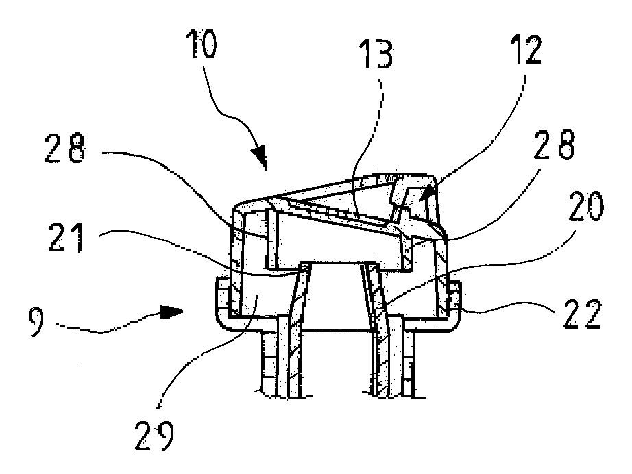
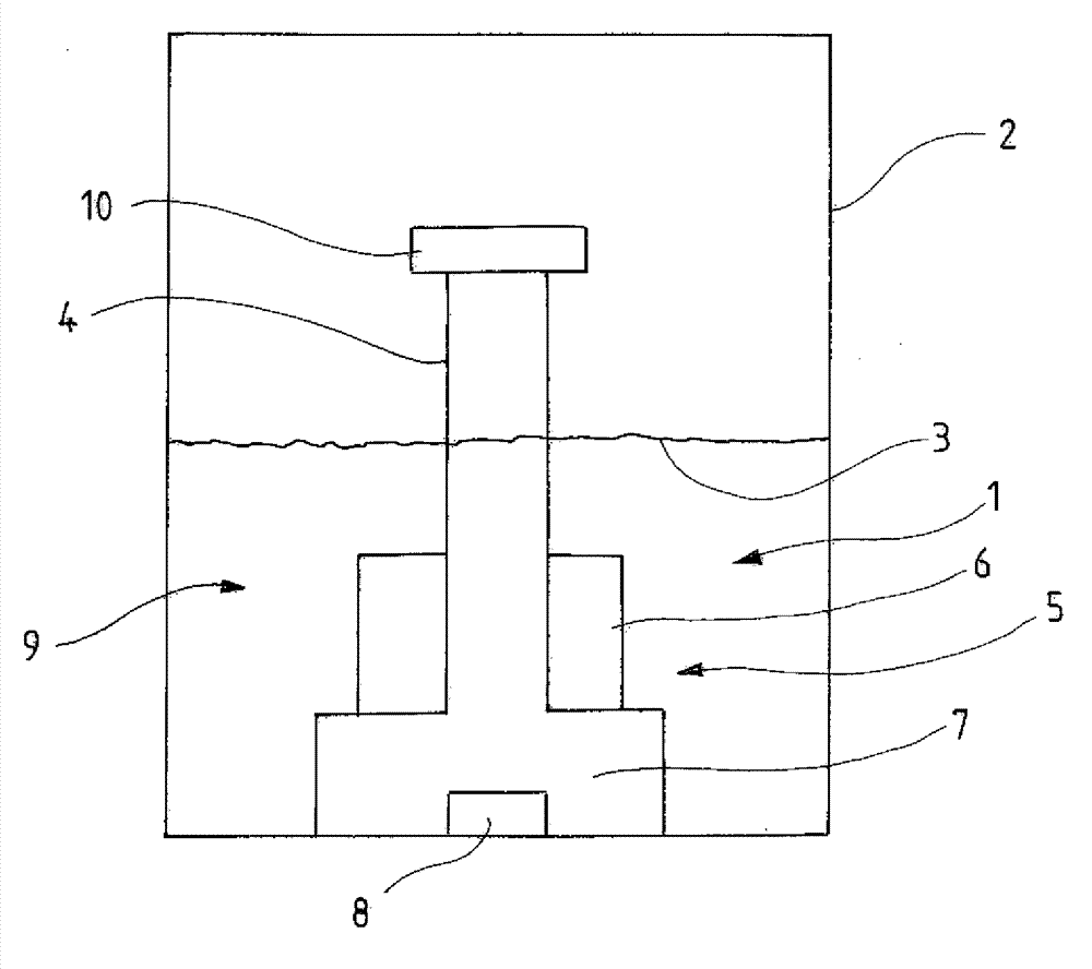
[0021] figure 1 A principal view representing the elements of the device 1 according to the invention. The device 1 according to the invention is arranged in a container 2 to measure the fill level 3 of a liquid in this container 2 . The device 1 comprises an antechamber 5 consisting here of a first antechamber 6 and a second antechamber 7 . An ultrasonic transducer 7 is arranged in the antechamber 5, here in the second antechamber 7, and this transducer is arranged below the measuring section 4 extending vertically upwards and emits ultrasonic waves in the upward direction, which are transmitted by the liquid Fill level 3 between the gas and the reflection at the boundary surface formed. Numeral 9 denotes a damping cup, which here represents an essential part of the device 1 . The damping cup 9 has fitted thereto a cap 10 which closes the damping cup 9 at the top and which includes a drain opening 12 .

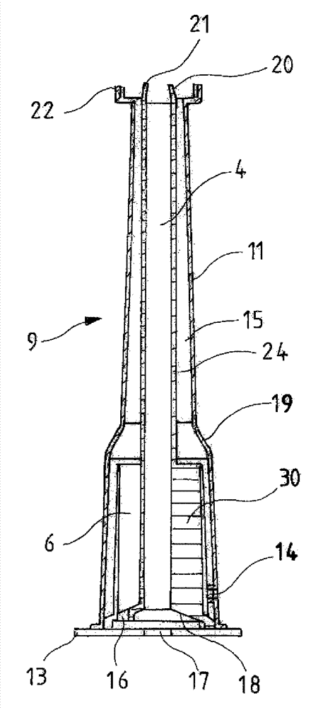
[0022] exist figure 2 In , the damper cup 9 is shown in perspectiv...


PUM


Abstract

A device for determining a filling level of a container is provided, having a damping cup, a measuring section extending vertically inside the damping cup, and having an ultrasound converter arranged at its lower end region, and at least one antechamber. A calming structure is arranged in at least a part of at least one antechamber, to achieve as much degassing of the liquid as possible. The part of the antechamber having the calming structure is designed to be open towards the top over a large area and is connected, via a venting channel, with a vent in the upper region of the device.

Description

technical field [0001] The invention relates to a device for determining the filling level of a container, comprising: a damping cup; a measuring section extending vertically inside the damping cup, and the measuring section has a damping cup arranged at its lower end region an ultrasound transducer; and at least one antechamber, wherein the stationary structure is disposed in at least a portion of the at least one antechamber. Background technique [0002] Such devices are known, for example, from DE 10 2010 011 492 A1 and DE 10 2008 027 969 A1. Ultrasonic sensors are often used to check the oil level in the engine. These emitted sound waves are reflected at a boundary surface between two media such as air and oil (where instead of oil other liquids can also be measured) and are received again by the ultrasonic sensor. The fill level in the container comprising the device can be determined from the recorded travel time of the sound waves. But when the engine is running, ...

Claims


Application Information

Patent Timeline
Patent Type & Authority Applications(China)
IPC IPC(8): G01F23/296
CPCF01M11/12G01F23/2962F01M11/06F02D1/00G01F23/0046B60K2015/03217
Inventor T.尼曼J.帕洛克斯
Owner HELLA KG HUECK & CO
Why Eureka
Try Eureka