Glove box

a glove box and glove technology, applied in the field of glove boxes, can solve the problems of difficult to keep the respective contents of impurities inside the glove box less than 1 ppm (parts per million), and the purity of the glove box operating space is assured, and the effect of effectively blocking external contaminants

Active Publication Date: 2013-11-12
VIGOR GAS PURIFICATION TECHNOLOGIES (SUZHOU) CO LTD
View PDF15 Cites 6 Cited by
  • Summary
  • Abstract
  • Description
  • Claims
  • Application Information

AI Technical Summary

Benefits of technology

[0019]The prominent substantive features and the notable progress of the present invention are as follows: By implementing the glove box of the present invention, a leakage shielding space can be formed between the main box body and the view window, or between the main box body and the side panel, or between the view window and the glove port, or between the glove port and the glove, or between the side panel and the antechamber, so as to ensure the purity in the operating space of the glove box and to effectively block the external contaminants from leaking inside due to the existence of gaps, so as to keep the moisture impurity less than 1 ppm and the oxygen impurity less than 1 ppm to maintain the degree of purity of gas. On the other hand, by implementing the glove box of the present invention, harmful substances inside the glove box will be blocked from leaking outwards due to the existence of gaps, so as to prevent the environment outside the glove box from being polluted. The present invention is easy to be implemented, and has made improvements in this technical field.

Problems solved by technology

Existing glove boxes have leakage issues, and it is difficult to keep the respective contents of impurities (such as moisture, oxygen) inside the glove box less than 1 ppm (parts per million), even if the glove box is filled with high purity gas.
1) Air can leak into the glove box through tiny gaps. The interfaces between the main box body and the view window, and between the glove and the glove port are normally sealed with rubber sealing rings, and there always exist tiny gaps around the sealing rings.
2) The oxygen and moisture in air can permeate into the glove box through the glove and the sealing rings. The glove and sealing rings are all rubber products, air can permeate slowly into the glove box through the rubber glove and rubber sealing rings.
3) When materials and devices are transferred into the glove box from outside, a small of amount of moisture and oxygen will be taken into as well. All materials can adsorb oxygen and moisture. Even though those materials have been evacuated in the antechamber before being transferred into the glove box, as shown in FIG. 1, remaining moisture and oxygen in the materials can only be removed very slowly by evacuation alone, and moisture and oxygen will be released gradually after the materials are transferred into the glove box.
Air has oxygen concentration of higher than 200,000 ppm and can easily leak into the glove box through tiny gaps to greatly affect the gas purity inside the box.

Method used


Image

  • Glove box
  • Glove box
  • Glove box

Examples


embodiment 1

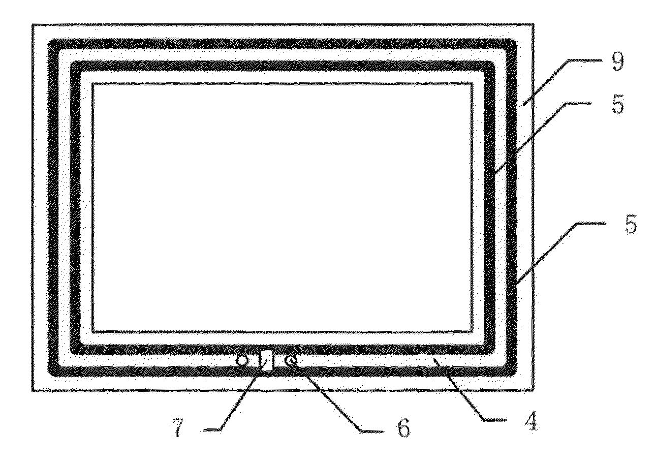
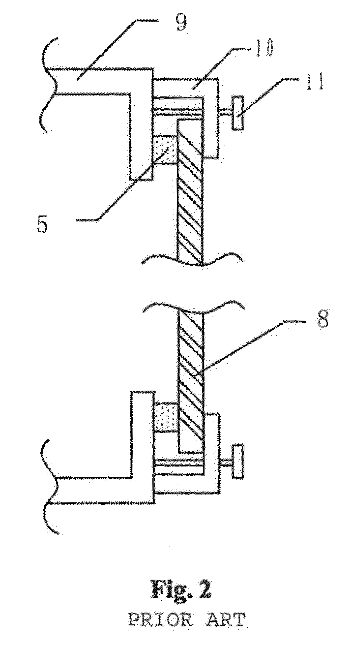
[0034]As shown in FIG. 3 and FIG. 5, the opening of the main box body has an inside edge 9 at its periphery, and two concentric circular sealing rings 5 are placed on the inside edge 9, the view window 8 is fitted over the sealing rings 5. The two sealing rings 5, together with the inside edge 9 and the view window 8, form a leakage shielding space 4. Specifically, the view window 8 is made of glass or plastic, and is securely attached, at its periphery, to the main box body by a holding stripe 10 and screws 11. In a similar way, a leakage shielding space 4 can be formed between the main box body and the side panel, or between the view window and the glove port, or between the side panel and the antechamber. Of course, the connection between the main box body and the side panel, and the connection between the side panel and the antechamber, can be realized by welding as done traditionally, and a relatively tight sealing effect can be obtained.

[0035]As shown in FIG. 3, to further ens...

embodiment 2

[0036]As shown in FIG. 4 and FIG. 5, the opening of the main box body has an inside edge 9 at its periphery, and two concentric circular sealing rings 5 are placed on the inside edge 9, the view window 8 is fitted over the sealing rings 5. The two sealing rings 5, together with the inside edge 9 and the view window 8, form a leakage shielding space 4. Specifically, the view window 8 is made of glass or plastic, and is securely attached, at its periphery, to the main box body by a holding stripe 10 and screws 11. In a similar way, a leakage shielding space 4 can be formed between the main box body and the side panel, or between the view window and the glove port, or between the side panel and the antechamber.

[0037]As shown in FIG. 4, to further ensure the leakage proof effect of the leakage shielding space during the use of the glove box, two through holes 6 are opened to the leakage shielding space 4, and the two through holes are separated by a spacer 7. Moreover, one of the throug...

embodiment 3

[0038]As shown in FIG. 7, the main box body has, at its interface sealed with the sealing ring 5, a drainage groove, such that a leakage shielding space 4 is formed between the drainage groove and the sealing ring 5. Furthermore, in order to create a leakage shielding space on other interfaces of the main box body, the main box body and the side panel also have drainage grooves at their contact surface sealed with the sealing rings 5, such that a leakage shielding space 4 is formed between the drainage groove and the sealing ring 5. The glove port may also, on its contact surface with a glove mounted thereon, have a drainage groove, such that a leakage shielding space 4 is formed between the drainage groove and the glove. If the antechamber and the side panel of the glove box are not connected by conventional welding, the side panel and the antechamber may also have drainage grooves on their contact surfaces sealed with the sealing rings 5, such that a leakage shielding space 4 is f...


PUM


Abstract

A glove box with a leakage shielding space (4) comprises a main box body, a view window (8) placed on the main box body, glove ports installed on the view window (8), side panels attached to the main box body, and an antechamber (1) installed on a side panel. Wherein, on at least one of five interfaces, namely, between the main box body and the view window (8), between the main box body and the side panel, between the view window (8) and the glove port, between the glove port and the glove, between the side panel and the antechamber (1), a leakage shielding space (4) is formed, so as to ensure the purity in the operating space of the glove box and to prevent the external environment of the box body from being polluted.

Description

TECHNICAL FIELD[0001]The present invention relates to a glove box and especially to a glove box with leakage shielding space, belonging to the technical field of a glove box system.BACKGROUND OF THE INVENTION[0002]In the process of scientific research and production, some materials are sensitive to one certain or several active compositions in air, such as oxygen, moisture, carbon dioxide and so on, and thus these research and production should be done in a sealed space filled with inert gases. On the other hand, some materials, which could be harmful to the operators if they are exposed to, should be dealt with in a sealed environment. A glove box, which can be made of metals or plastics, is a typical example of this like device, including a main box body having multiple openings equipped thereon with a view window, an antechamber, glove ports and so on. Operators operate the materials and devices inside the box body through a glove, and the antechamber is used for transferring mat...

Claims


Application Information

Patent Timeline
Patent Type & Authority Patents(United States)
IPC IPC(8): B25J21/02
CPCB25J21/02
Inventor ZHANG, DELONG
Owner VIGOR GAS PURIFICATION TECHNOLOGIES (SUZHOU) CO LTD
Why Eureka
Try Eureka