Measuring container for biomagnetic measurements

a biomagnetic and container technology, applied in the field of measuring containers for biomagnetic measurements, can solve the problems of inability to avoid providing appropriate screening against electromagnetic and/or magnetic fields, the measurement of magnetic fields of biological samples or patients, and the measurement of temporal changes in these magnetic fields constitutes a substantial challenge, and achieves the effect of efficient screening

Inactive Publication Date: 2010-04-15
BMDSYS PRODN
View PDF3 Cites 5 Cited by
  • Summary
  • Abstract
  • Description
  • Claims
  • Application Information

AI Technical Summary

Benefits of technology

[0017]It is therefore an object of the present invention to provide a screen for biomagnetic measurements which can be used, in particular, for magnetocardiological measurements. The screen is intended, on the one hand, to offer efficient screening against high frequency fields and, preferably, also against low frequency magnetic fields which is, for example, intended to relax the requirements placed on the measurement electronics. At the same time, however, the screening is to be easy to handle, preferably transportable and quick to integrate, in order to open up biomagnetic measurements to a wider field of application than has so far been the case.

Problems solved by technology

The measurement of magnetic fields of biological samples or patients, and / or the measurement of temporal changes in these magnetic fields constitutes a substantial challenge, however, in terms of measurement technology.
However, this readout electronics reacts sensitively to parasitic external electromagnetic fields which can cause strong disturbances.
However, it has emerged in practice that despite an improved input filtering the signals of biomagnetic measurements can continue to be subject to strong influences from external electromagnetic and magnetic fields, since the abovementioned filters only facilitate the operation of the sensors, but generally have no effect on the electromagnetic disturbances in the frequency range of the biomagnetic signals to be measured.
Consequently, it is impossible in practice in many cases to avoid provision of appropriate screening against the electromagnetic and / or magnetic fields.
However, the screening chamber described in EP 0 359 864 B1 is extremely complicated in practice.
A particular disadvantage of the device described in EP 0 359 864 B1 presides in the fact that despite the complicated screening numerous connections exist between the inner region of the screening chamber and the outer region, these being caused, for example, by leading the patient couch holder through the ground screen, and by further numerous posts led through the screening and by electrical bushings.
These bushings have the effect, however, that magnetic and electromagnetic fields are coupled into the interior of the screening chamber and can sensitively impair measurement there.
A particular set of problems of the known screening chambers is, furthermore, in the arrangement of the required measurement electronics and / or of the computer systems required for the evaluation, in particular an image evaluation.
If the measurement electronics and the computer systems are arranged entirely or partially in the interior of the screening chamber, they then disturb the measurements of electromagnetic fields generated by the electronics and / or computer systems.
In addition, it is thereby impossible in practice in this case to operate the computer systems during the actual measurement, since the operating staff should not stay in the screening chamber during measurement, in order not to influence the measurement.
A further set of problems of such known screening chambers is that it is necessary to ensure that the patient is taken care of at all times, particularly in the field of magnetocardiography.
However, in the interior of a screening chamber—for example such as the screening chamber described in EP 0 359 864 B1, provision of such care is scarcely possible in practice since, for example, the application of a defibrillator would also simultaneously damage the sensor systems and / or the measurement electronics, and would thus occasion substantial costs.
In addition, the space required for emergency medical care is lacking in most screening chambers.

Method used


Image

  • Measuring container for biomagnetic measurements
  • Measuring container for biomagnetic measurements
  • Measuring container for biomagnetic measurements

Examples


Embodiment Construction

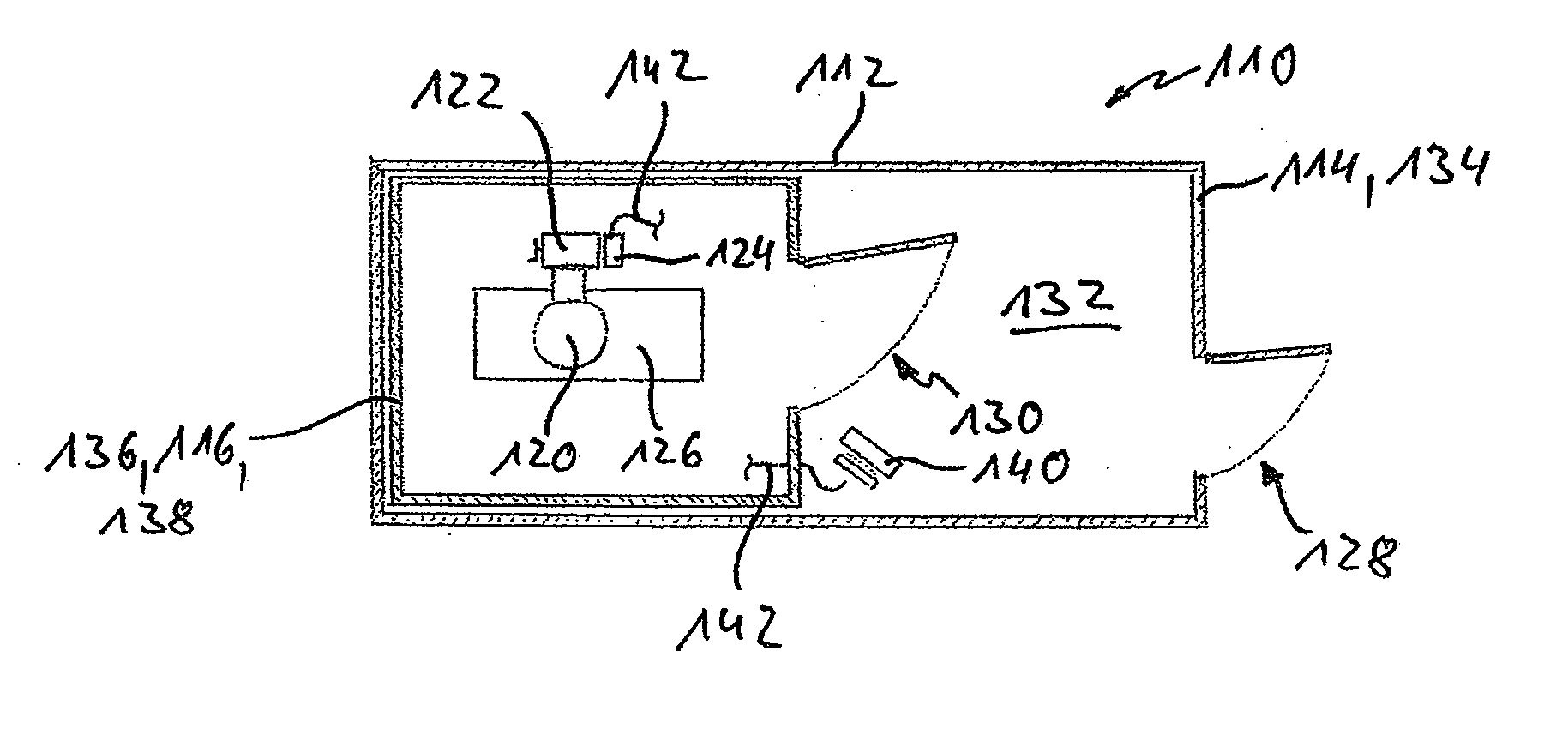
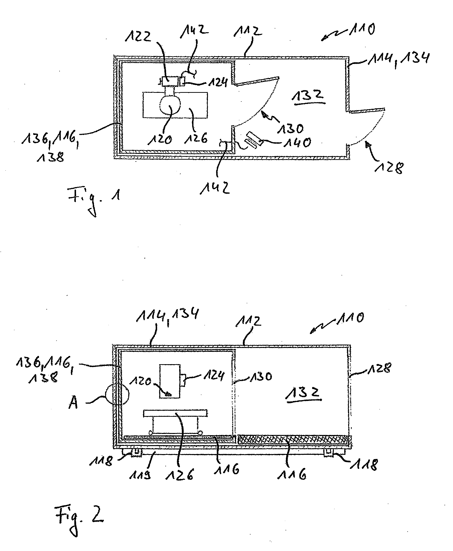
[0048]An exemplary embodiment of an inventive biomagnetic measuring system 110 is illustrated in FIGS. 1 and 2. The biomagnetic measuring system 110 comprises an exemplary embodiment of an inventive measuring container 112 which is illustrated in FIG. 1 in a sectional illustration in a view from above, and is illustrated in FIG. 2 in a sectional illustration in a view from the side.

[0049]According to the invention, the measuring container 112 can be constructed as a two-chamber system and comprises an outer container 114 into which a measuring chamber 116 is introduced.

[0050]The outer container 114 can, for example, be designed as a standard container and can, for example, be loaded onto a lorry, fastened there and transported in this way. To this end, for example, it is possible to provide on the outer container 114 appropriate transport elements 118 which are known to the person skilled in the art. For example, these can be standard transport elements by means of which the measuri...


PUM


Abstract

A measuring container is provided, which can be used for biomagnetic measurements, in particular for magnetocardiological measurements. The measuring container comprises an outer screen against electromagnetic high frequency fields and an inner screen against low frequency electromagnetic fields. The measuring container is constructed as a two-chamber system with an outer container comprising the outer screen. A measuring chamber with the inner screen is introduced into the outer container. An antechamber which can be walked into from outside is formed between the inner wall of the outer container and the measuring chamber.

Description

[0001]This nonprovisional application is a continuation of International Application No. PCT / EP2008 / 001091, which was filed on Feb. 13, 2008, and which claims priority to German Patent Application No. 10 2007 017 316.6, which was filed in Germany on Apr. 11, 2007, and which are both herein incorporated by reference.BACKGROUND OF THE INVENTION[0002]1. Field of the Invention[0003]The invention relates to a measuring container for biomagnetic measurements which can be used, in particular, for magnetocardiological measurements. Furthermore, the invention relates to a biomagnetic measuring system which comprises a measuring container according to the invention. Such measuring containers and biomagnetic measuring systems can be used, in particular, in the field of cardiology, but also in other medical fields, such as neurology, for example. Other applications are, however, also conceivable.[0004]2. Description of the Background Art[0005]In recent years and decades, magnetic measuring syst...

Claims


Application Information

Patent Timeline
Patent Type & Authority Applications(United States)
IPC IPC(8): A61B5/05G01R33/02G01R33/12
CPCH05K9/0001A61B5/04007A61B5/243
Inventor KRUEMMEL, TORSTEN
Owner BMDSYS PRODN
Why Eureka
Try Eureka