Distance measuring method of significant target in binocular image

A technology in distance measurement and image, applied in the field of image processing, which can solve problems such as slow processing speed

Active Publication Date: 2015-07-15
GUANGZHOU XIAOPENG MOTORS TECH CO LTD
View PDF2 Cites 30 Cited by
  • Summary
  • Abstract
  • Description
  • Claims
  • Application Information

AI Technical Summary

Problems solved by technology

[0004] The purpose of the present invention is to propose a distance measurement method of a salient target in a binocular image, to solve the problem of slow processing speed of the existing target distance measurement method

Method used


Image

  • Distance measuring method of significant target in binocular image
  • Distance measuring method of significant target in binocular image
  • Distance measuring method of significant target in binocular image

Examples


specific Embodiment approach 1

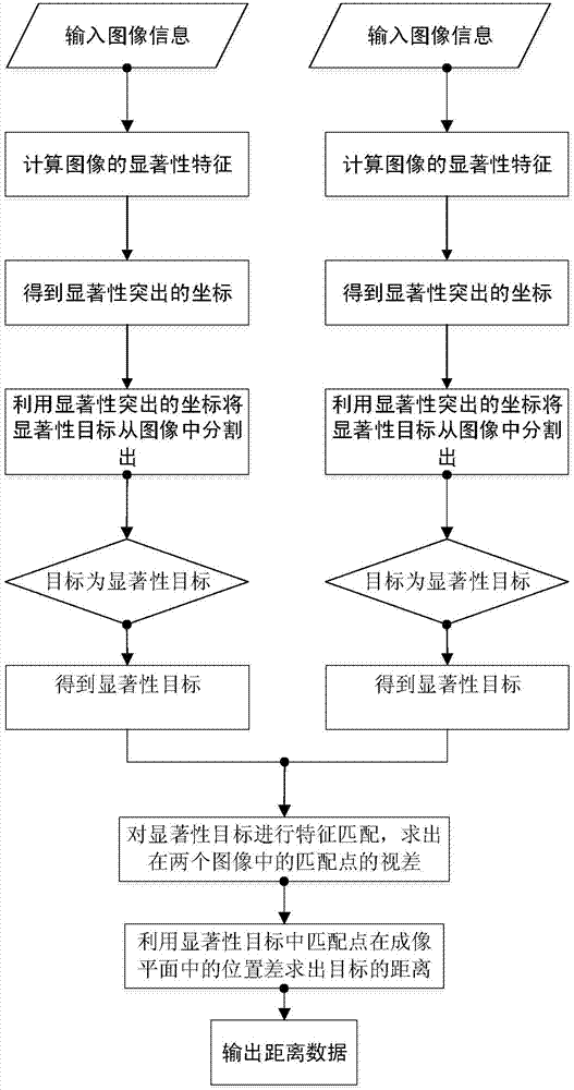
[0096] Specific implementation mode one: the following combination Figure 1 to Figure 5 To illustrate this embodiment, the method described in this embodiment includes the following steps:

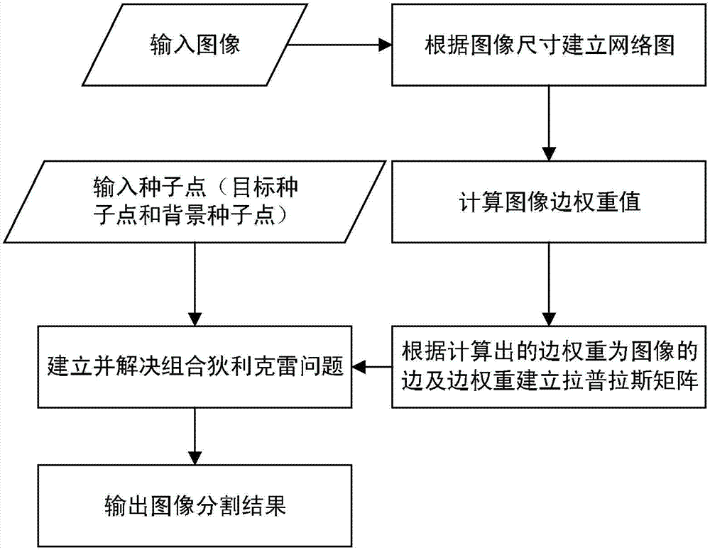
[0097] Step 1. Use the visual saliency model to extract the saliency features of the binocular image, and mark the seed points and background points, specifically including:

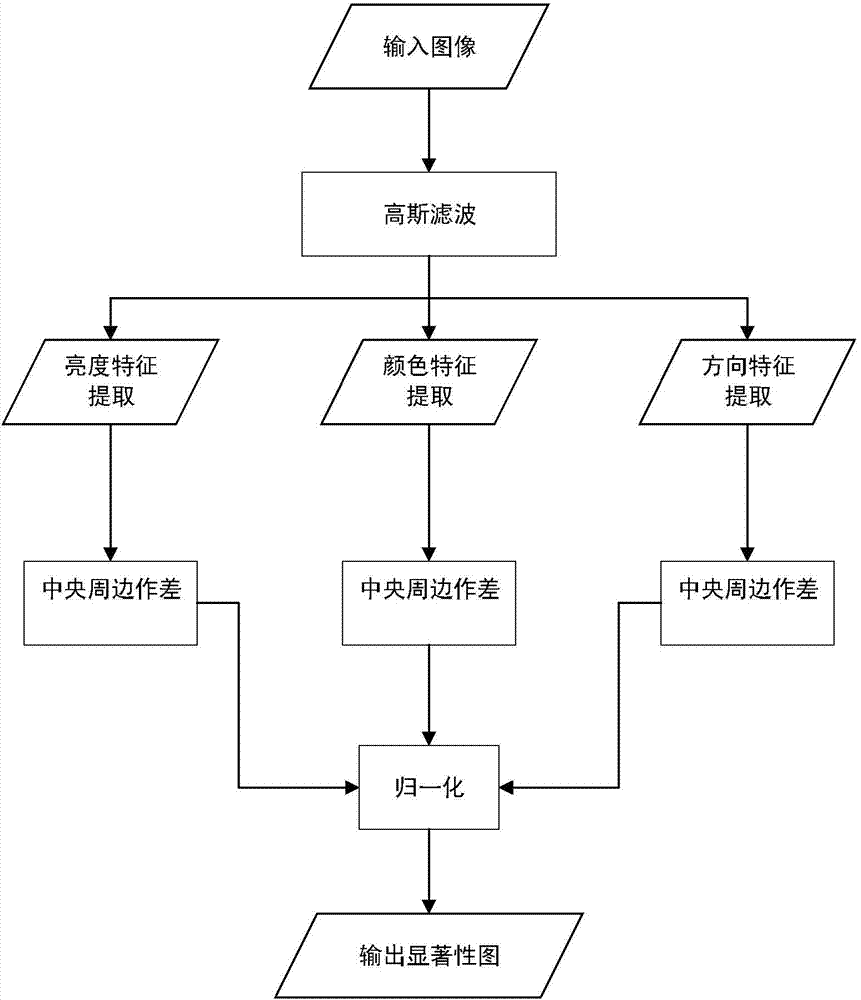
[0098] The visual saliency model is used to extract the saliency of the binocular image, and the three salient features of brightness, color, and direction of each pixel of the binocular image are calculated respectively, and the three salient features are normalized to obtain the weighted saliency of the image picture. Each pixel on the saliency map represents the saliency of the corresponding position in the image. Find the point with the largest pixel value in the picture, that is, the point with the strongest significance, and mark it as a seed point; gradually expand the range around the seed point to find th...

specific Embodiment approach 2

[0184] Specific embodiment two: the present embodiment is described below in conjunction with the figure, and the difference between this embodiment and the specific embodiment one is: the specific process of performing edge detection on the image described in step one by one is:

[0185] Step 111, using 2D Gaussian filter template to perform convolution operation on the binocular image to eliminate the noise interference of the image;

[0186] Step 112, using the difference of the first-order partial derivatives in the horizontal and vertical directions to calculate the gradient magnitude and gradient direction of the pixel on the filtered binocular image I(x, y) respectively, where the partial derivatives in the x direction and y direction The derivatives dx and dy are respectively:

[0187] dx=[I(x+1,y)-I(x-1,y)] / 2 (21)

[0188] dy=[I(x,y+1)-I(x,y-1)] / 2 (22)

[0189] Then the gradient magnitude is:

[0190] D'=(dx 2 +dy 2 ) 1 / 2 (twenty three)

[0191] The gradient d...

specific Embodiment approach 3

[0195] Specific embodiment three: The following describes this embodiment in conjunction with the figures. The difference between this embodiment and specific embodiment one or two is that: the use of the visual saliency model to extract the salient features of the binocular image described in step 12 generates a salient feature. The specific process of the characteristic map is as follows:

[0196] Step 121, after binocular image edge detection, superimpose the original image and the edge image:

[0197] I 1 (σ)=0.7I(σ)+0.3C(σ) (25)

[0198] Among them, I(σ) is the original image of the input binocular image, C(σ) is the edge image, I 1 (σ) is the image after superposition processing;

[0199] Step 122: Use the Gaussian difference function to calculate the nine-layer Gaussian pyramid of the superimposed image, wherein the 0th layer is the input superimposed image, and the 1st to 8th layers are respectively formed by using Gaussian filtering and downsampling on the previous...


PUM


Abstract

The invention relates to a distance measuring method of a significant target in a binocular image. The distance measuring method of the significant target in the binocular image aims to solve the problem that an existing target distance measuring method is low in the processing speed. The method includes the steps that step 1, significant feature extraction is conducted on the binocular image through a visual significance model, and a seed point and a background point are marked; step 2, a weighed graph is established for the binocular image; step 3, a significant target in the binocular image is partitioned through a random walk image partitioning algorithm by means of the seed point and the background point in step 1 and the weighed graph in step 2; step 4, key point matching is conducted on the significant target separately through an SIFT algorithm; step 5, the significant target distance is worked out by applying a parallax matrix K' worked out in step 4 into a binocular distance measuring model. The distance measuring method can be applied to distance measurement of the significant target of the image in front of the vision in the intelligent automobile running process.

Description

technical field [0001] The invention relates to a distance measurement method for a target in a binocular image, in particular to a distance measurement method for a salient target in a binocular image, and belongs to the technical field of image processing. Background technique [0002] Distance information is mainly used in traffic image processing to provide safety judgments for vehicle control systems. In the research process of smart cars, the traditional target measurement method is to use specific wavelength radar or laser to measure the distance of the target. Compared with radar and laser, vision sensors have a price advantage, and at the same time, they have a wider viewing angle. And the visual sensor can be used to measure the distance of the target and at the same time, the specific content of the target can be judged. [0003] However, the current traffic image information is relatively complicated, and it is difficult for the traditional target distance meas...

Claims


Application Information

Patent Timeline
Patent Type & Authority Applications(China)
IPC IPC(8): G06T7/00
Inventor 王进祥杜奥博石金进
Owner GUANGZHOU XIAOPENG MOTORS TECH CO LTD
Why Eureka
Try Eureka