Dropper cap

a technology of dropper cap and droplet, which is applied in the direction of liquid dispensing, containers, pliable tubular containers, etc., can solve the problems that the liquid left behind on the exterior of the pour spout might otherwise be subject to airborne contamination or contamination, and achieve the effect of dispense single droplets, better and finer control of droplet size, and maintaining the ability to dispens

Inactive Publication Date: 2005-07-12
SEASTAR CHEM
View PDF14 Cites 6 Cited by
  • Summary
  • Abstract
  • Description
  • Claims
  • Application Information

AI Technical Summary

Benefits of technology

[0011]The improved dropper cap according to the invention provides better and finer control of the droplet size while maintaining the ability to dispense in a stream-like fashion. The minimum drop size dispensed is also much finer in the present invention than in the prior art caps. All of the liquid is dispensed precisely and is contained neatly and safely, and the invention can dispense single droplets, even in less viscous liquids.

Problems solved by technology

Liquid left behind on the exterior of the pour spout might otherwise be subject to airborne contamination or contamination from subsequent handling.

Method used


Image

  • Dropper cap
  • Dropper cap
  • Dropper cap

Examples


Embodiment Construction

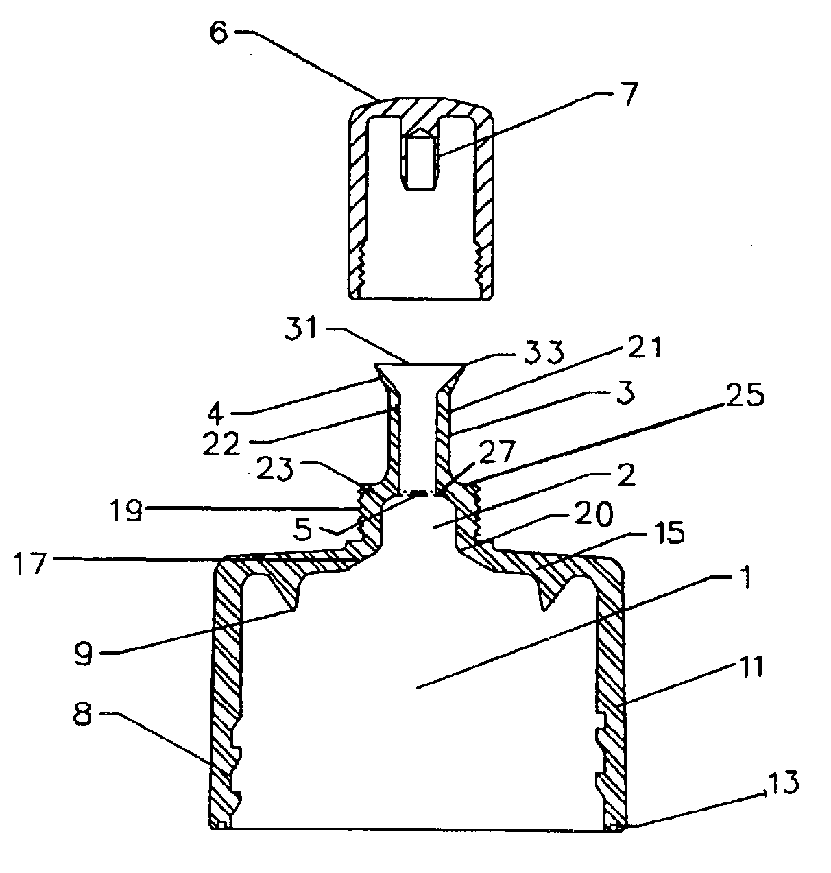
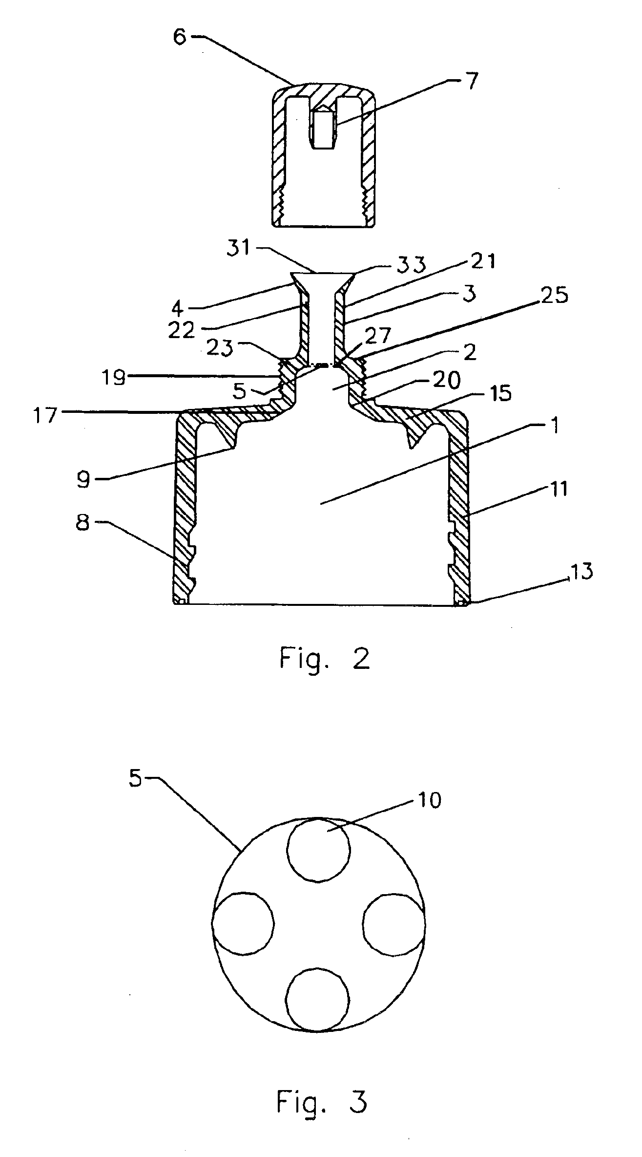
[0028]FIG. 2 shows the preferred embodiment of the present invention. The preferred embodiment includes a chamber 1 defined by a substantially cylindrical chamber wall 11 and a top surface 15. At one end, cylindrical chamber wall 11 is contiguous with the top surface 15, while at the opposite end it terminates as a free end 13 forming the first open, inlet end of chamber 1. Top surface 15 extends radially inward from the cylindrical chamber wall 11 and defines an antechamber opening 20 at a second, outlet end of chamber 1. The inner surface of cylindrical chamber wall 11 is provided with a threaded element 8 for attachment to a container. The diameter of the chamber 1 is slightly larger than the top of the container, such that the cap fits snugly over the top of the container. The container is typically of the form of a plastic bottle with a flexible wall.

[0029]An open-ended antechamber 2 is defined by a cylindrical antechamber wall 19 and upper surface 25. From antechamber opening ...


PUM


Abstract

An improved dropper cap, for use in controlled dispensing of liquid from a container, comprises an antechamber, a baffle and an elongated nozzle. The nozzle may comprise a flared spout to ensure clean separation of the liquid from the dropper cap, reducing dripping and smearing of the liquid on the dropper cap, as well as precise dispensing of the liquid. The baffle physically prevents splashing of the liquid from the container, and includes openings to control the flow of liquid into the nozzle. The baffle and antechamber cooperate to draw back undispensed liquid from the nozzle and prevent spurting of the liquid from the container between uses. Further, the dropper cap is threaded to allow easy attachment and removal from the container.

Description

FIELD OF THE INVENTION[0001]This invention relates to a dropper cap for the controlled dispensing of liquids from an associated liquid container at a controlled flow rate, from individual droplets through the flow range to a steady stream, in a controlled and neat fashion, without spillage or contamination of the liquid.BACKGROUND OF THE INVENTION[0002]Liquids are dispensed from liquid containers in a variety of means, depending upon the physical properties of the liquid being poured and on the ease and / or accuracy of dispensing being sought. The dispensing means ranges from the ubiquitous mustard dispenser or liquid dishwashing detergent dispenser to those used in the laboratory dispensing hazardous chemicals of an ultrapure nature. Amounts dispensed vary from single droplets to a steady stream. Their complexity varies from the plastic caps seen on household goods to mechanical pumps found in laboratories, which are devices that are typically based upon some form of piston and valv...

Claims


Application Information

Patent Timeline
Patent Type & Authority Patents(United States)
IPC IPC(8): B65D47/00B65D47/12B65D47/40
CPCB65D47/123B65D47/40
Inventor STUKAS, VIDAS
Owner SEASTAR CHEM
Why Eureka
Try Eureka