Lithium-ion secondary battery and method of charging lithium-ion secondary battery

a lithium-ion secondary battery and lithium-ion battery technology, applied in the direction of secondary cell servicing/maintenance, cell components, sustainable manufacturing/processing, etc., can solve the problem that the capacity keeping ratio after the cycle of charging/discharging is likely to deteriorate remarkably, and achieve the effect of less likely to deteriorate its capacity greatly

Inactive Publication Date: 2005-11-03
TDK CORPARATION
View PDF13 Cites 60 Cited by
  • Summary
  • Abstract
  • Description
  • Claims
  • Application Information

AI Technical Summary

Benefits of technology

[0006] Recently, rapid (high-rate) charging such as constant current / constant voltage charging at 10 C or higher or constant voltage charging has been proposed in order to shorten charging time. However, it has been found that the capacity keeping ratio after cycles of charging / discharging is likely to deteriorate remarkably when the above-mentioned rapid charging is performed in conventional lithium-ion secondary batteries such as those mentioned above.
[0008] As a result of diligent studies, the inventors have found that the capacity keeping ratio after cycles of charging / discharging can be made sufficiently high even when rapid charging is performed in the case where (1) the carried amount of a negative electrode active material disposed on a negative electrode collector falls within a predetermined range while (2) the air permeance and porosity of a separator fall within predetermined ranges, thereby achieving the present invention.
[0013] Thus configured lithium-ion secondary battery is less likely to deteriorate its capacity after cycles of charging / discharging even when charged rapidly. This enables constant voltage charging, for example, whereby portable devices and the like can improve their convenience.
[0014] The reason why the lithium-ion secondary battery of the present invention exhibits such a characteristic is not clear. However, it seems to be because of the fact that, since the negative electrode active material is carried less than that in conventional lithium-ion secondary batteries, the area of the interface between the active material and electrolytic solution is substantially enlarged, so that the Li concentration polarization decreases within the negative electrode active material layer, whereby lithium ions are less likely to be deposited as dendrite on the negative electrode; and because of the fact that the separator has physical properties falling within predetermined ranges, whereby lithium ions are allowed to migrate sufficiently and evenly.
[0016] Rapid charging can favorably be performed when the lithium-ion secondary battery is charged with a set current value corresponding to 10 C. or higher.
[0018] The present invention can realize a lithium-ion secondary battery which is less likely to deteriorate its capacity greatly after cycles of charging / discharging even when charged rapidly.

Problems solved by technology

However, it has been found that the capacity keeping ratio after cycles of charging / discharging is likely to deteriorate remarkably when the above-mentioned rapid charging is performed in conventional lithium-ion secondary batteries such as those mentioned above.

Method used


Image

  • Lithium-ion secondary battery and method of charging lithium-ion secondary battery
  • Lithium-ion secondary battery and method of charging lithium-ion secondary battery
  • Lithium-ion secondary battery and method of charging lithium-ion secondary battery

Examples


first embodiment

[0025] First, an embodiment of the lithium-ion secondary battery in accordance with the present invention will be explained in detail.

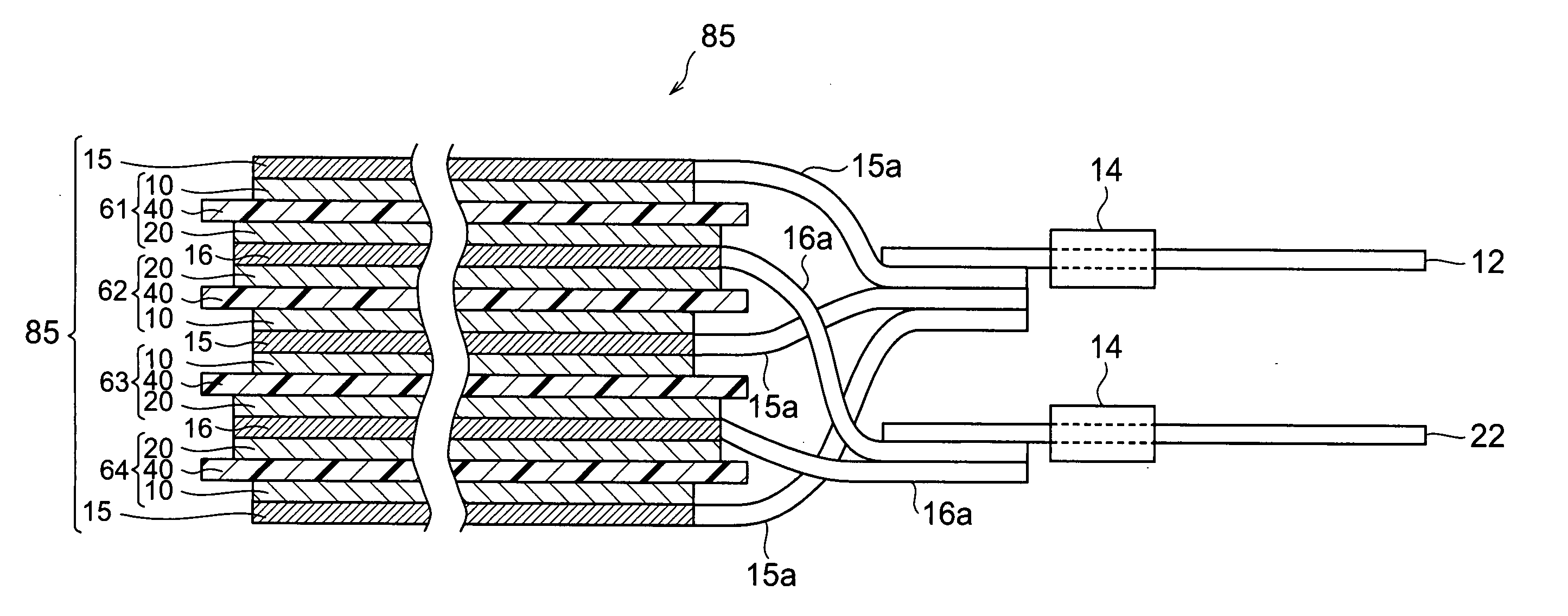
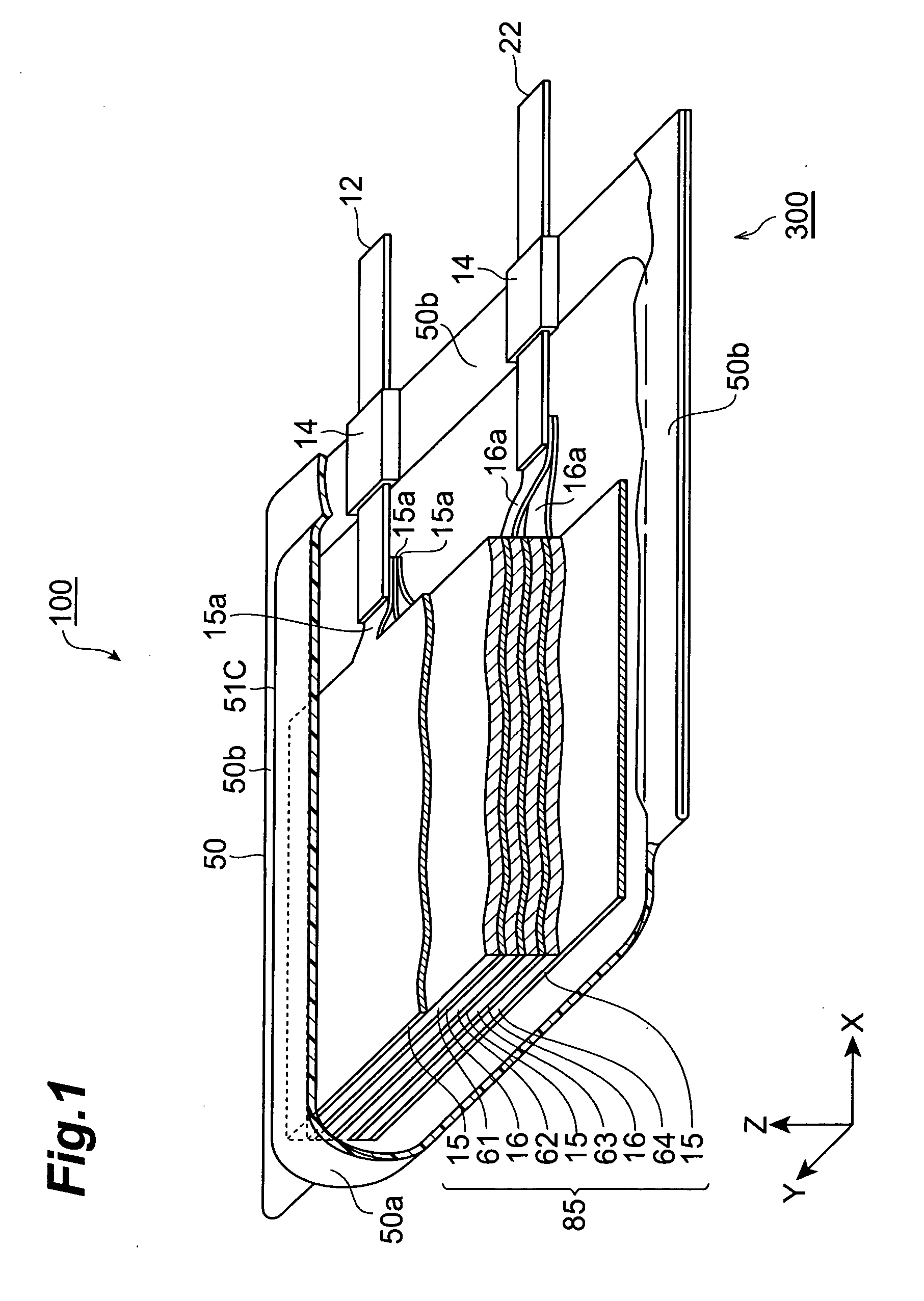
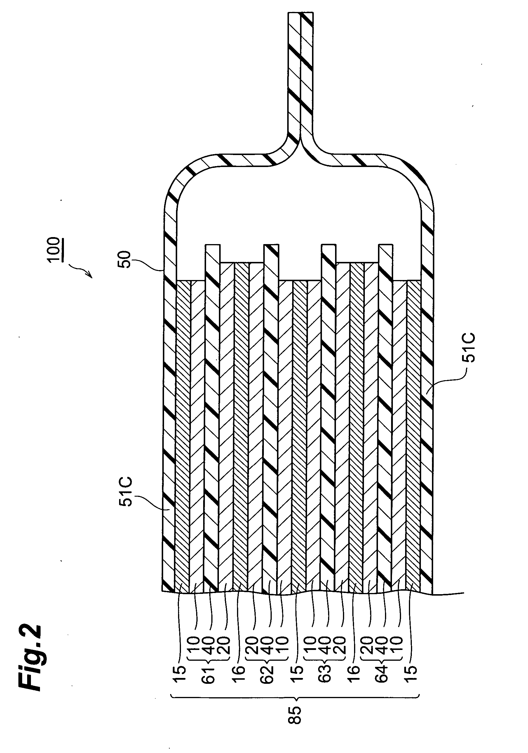
[0026]FIG. 1 is a partly broken perspective view showing a lithium-ion secondary battery 100 in accordance with a first embodiment of the present invention. FIG. 2 is a sectional view taken along the YZ plane of FIG. 1. FIG. 3 is a view showing a laminate structure 85 and leads 12 and 22 as seen in the ZX cross section of FIG. 1.

[0027] As shown in FIGS. 1 to 3, the lithium-ion secondary battery 100 in accordance with this embodiment is mainly constituted by a laminate structure 85; a case (package) 50 for accommodating the laminate structure 85 in a closed state; and leads 12 and 22 for connecting the laminate structure 85 to the outside of the case 50. The laminate structure 85 comprises, successively from the upper side, a positive electrode collector 15, a secondary battery element 61, a negative electrode collector 16, a secondary battery elemen...

example 1

[0094] First, cathode laminates were made in the following procedure. Initially, LiMn0.33Ni0.33CO0.34O2 (where the subscripts indicate atomic ratios) as a positive electrode active material, acetylene black as a conductive auxiliary agent, and polyvinylidene fluoride (PVdF) as a binder were prepared. They were mixed and dispersed by a planetary mixer such that the weight ratio of positive electrode active material / conductive auxiliary agent / binder =90:6:4. Then, the viscosity of the resulting product was adjusted with an appropriate amount of NMP as a solvent mixed therein, whereby a slurry-like cathode coating liquid (slurry) was prepared.

[0095] Subsequently, an aluminum foil (having a thickness of 20 μm) was prepared, and the cathode coating liquid was applied thereto by doctor blading such that the carried amount of the active material became 5.5 mg / cm2, and then was dried. Thus obtained product was pressed with calender rolls such that the applied cathode layer attained a poros...

example 2

[0103] The procedure was the same as Example 1 except that Solupor 8P07A manufactured by Teijin Solufill Co., Ltd. (having a thickness of 50 μm, a Gurley air permeation of 6 s / 100 cm3, and a porosity of 85%) was used as separators.


PUM

PropertyMeasurementUnit
porosityaaaaaaaaaa
constant voltageaaaaaaaaaa
crystallite size Lc002aaaaaaaaaa

Abstract

A lithium-ion secondary battery comprises a positive electrode collector having a surface provided with a positive electrode active material layer containing a positive electrode active material; a negative electrode collector having a surface provided with a negative electrode active material layer containing a negative electrode active material; an electrically insulating porous separator; and an electrolytic solution containing a lithium salt and infiltrating the separator. The negative electrode active material layer carries 2.0 to 6.0 mg / cm2 of the negative electrode active material. The separator has a porosity of 45% to 90% and a Gurley air permeance of less than 200 s / 100 cm3.

Description

BACKGROUND OF THE INVENTION [0001] 1. Field of the Invention [0002] The present invention relates to a lithium-ion secondary battery and a method of charging the same. [0003] 2. Related Background Art [0004] Along with recent dissemination and development of various portable devices, lithium-ion secondary batteries have been desired to further improve their characteristics. One of the characteristics expected to improve is the capacity keeping ratio after repeating a number of cycles of charging and discharging. [0005] There have conventionally been proposals for improving the capacity keeping ratio, for example, by optimizing active materials (Japanese Patent Application Laid-Open No. H 10-236809) and by thinning electrodes so as to increase the opposing area of positive and negative electrodes while shortening the ion migration distance within the electrodes (Japanese Patent Application Laid-Open No. 2002-231312). SUMMARY OF THE INVENTION [0006] Recently, rapid (high-rate) chargin...

Claims


Application Information

Patent Timeline
Patent Type & Authority Applications(United States)
IPC IPC(8): H01M4/13H01M10/04H01M10/05H01M10/052H01M10/42H01M10/44H01M50/417H01M50/489H01M50/491
CPCH01M2/162H01M4/485H01M4/505H01M4/525Y02E60/122H01M10/0525H01M10/44H01M2010/4292H01M10/0436Y02E60/10H01M50/44Y02P70/50H01M50/417H01M50/491H01M50/489
Inventor OGAWA, KAZUYAIIJIMA, TSUYOSHIMARUYAMA, SATOSHI
Owner TDK CORPARATION
Why Eureka
Try Eureka