Method and electronic circuit for efficient battery wake up charging

Inactive Publication Date: 2006-06-29
O2 MICRO INT LTD
View PDF5 Cites 44 Cited by
  • Summary
  • Abstract
  • Description
  • Claims
  • Application Information

AI Technical Summary

Benefits of technology

[0010] The present invention advantageously provides a method and a circuit for efficient battery

Problems solved by technology

Since the output voltage of the ACDC adapter has a fixed value while the output voltage of the battery may vary largely (depending on its charged state) the ACDC adapter and the battery can not be coupled in parallel to supply power to the system load at certain times. This difference in voltage would lead to undesirable inter-current flow from the higher voltage source (ACDC adapter) to the lower voltage source (battery).
As a result, in order to acco

Method used


Image

  • Method and electronic circuit for efficient battery wake up charging
  • Method and electronic circuit for efficient battery wake up charging
  • Method and electronic circuit for efficient battery wake up charging

Examples


Embodiment Construction

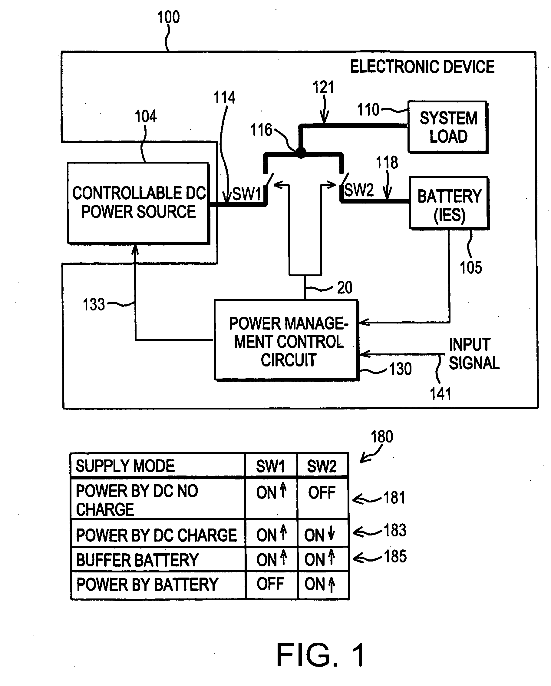
[0039]FIG. 1 illustrates a simplified block diagram of an electronic device 100 having a system load 110 capable of being powered by a controllable DC power source 104, a battery 105, or by both in parallel as the need arises as further detailed herein. A table 180 showing the position of switches SW1 and SW2 in various power supply modes is also illustrated. In one embodiment, the controllable DC power source 104 may be a controllable adapter as further detailed herein, e.g., an ACDC adapter, that provides the only power conversion necessary to deliver power to the system load 110 and the battery 105. As such, the need for an additional power conversion step (e.g., a DC to DC converter to provide a finely controlled output to the battery for charging) typically utilized in other power supply systems is obviated in this instance.

[0040] The electronic device 100 may be any variety of devices known in the art such as a laptop computer, cell phone, personal digital assistant, power to...


PUM


Abstract

A method for efficiently charging a battery. The method includes producing a first signal having a voltage level dependent on the voltage of the battery, comparing the voltage level of the first signal with a settable voltage representative of a maximum battery charging current, and producing a second signal representative of a charging current to be provided to the battery, the second signal having a voltage level selected to be the lower voltage level between the first signal and the settable voltage.

Description

CROSS REFERENCE TO RELATED APPLICATIONS [0001] This application is a continuation-in-part of U.S. patent application Ser. No. 10 / 812,802, “POWER MANAGEMENT TOPOLOGIES,” filed on Mar. 30, 2004, which itself is a continuation-in-part application of U.S. patent application Ser. No. 10 / 652,110 “POWER MANAGEMENT TOPOLOGIES,” filed on Aug. 29, 2003, the teaching of which is hereby incorporated in their entirety by reference. The U.S. patent application Ser. No. 10 / 652,110 is a continuation-in-part application of U.S. patent application Ser. No. 10 / 364,228 filed Feb. 11, 2003, now U.S. Pat. No. 6,977,482 “SELECTOR CIRCUIT FOR POWER MANAGEMENT IN MULTIPLE BATTERY SYSTEMS” issued on Dec. 20, 2005, the teachings of which are incorporated herein by reference, and claims the benefit of the filing date of the U.S. Provisional Patent Application Ser. No. 60 / 484,635, filed on Jul. 3, 2003, the teachings of which are also incorporated herein by reference. The U.S. patent application Ser. No. 10 / 652...

Claims


Application Information

Patent Timeline
IPC IPC(8): H02J7/00
CPCH02J7/0013H02J7/0018H02J7/0027H02J7/0057H02J7/0068H02J7/0075Y02T10/7055H02J7/045H02J7/34H02J9/061H02J2007/0059H02J2007/0067H02M2001/0045H02J7/02H02J7/0069H02J2207/20H02J7/0025Y02T10/70H02J7/04H02M1/0045H02J7/00714H02J7/007182H02J5/00
Inventor NICULAE, MARIANBUCUR, CONSTANTIN
Owner O2 MICRO INT LTD
Why Eureka
Try Eureka