Battery charging and handling system for electric vehicles

a technology for electric vehicles and charging systems, applied in vehicle maintenance, secondary cell servicing/maintenance, electrochemical generators, etc., can solve the problems of affecting the charging efficiency of electric vehicles, and requiring long charging time for batteries. to achieve the effect of efficient battery charging managemen

Inactive Publication Date: 2000-07-25
IND TECH RES INST
View PDF7 Cites 151 Cited by
  • Summary
  • Abstract
  • Description
  • Claims
  • Application Information

AI Technical Summary

Benefits of technology

It is an object of the present invention to provide a battery charging and transferring system wherein the charging of the battery can be more efficiently managed and the most fully charged battery is loaded on the electric vehicle.

Problems solved by technology

However, the present battery for electric vehicle is generally bulky and hard to be carried manually, and the charging of such battery requires long time.
FIG. 2 shows the perspective view of U.S. Pat. No. 5,711,648, this system still has the problem of different initial battery charging condition, the fully-charged battery may be blocked by those batteries requiring long charging time.
Therefore, this system has defective efficiency.
Therefore, large number of stand-by batteries are required and the arrangement of battery is less flexible.
This problem is worsen for smaller work space such as trailer.
It is difficult to pick up the defective battery during the charging operation.

Method used


Image

  • Battery charging and handling system for electric vehicles
  • Battery charging and handling system for electric vehicles
  • Battery charging and handling system for electric vehicles

Examples


first embodiment

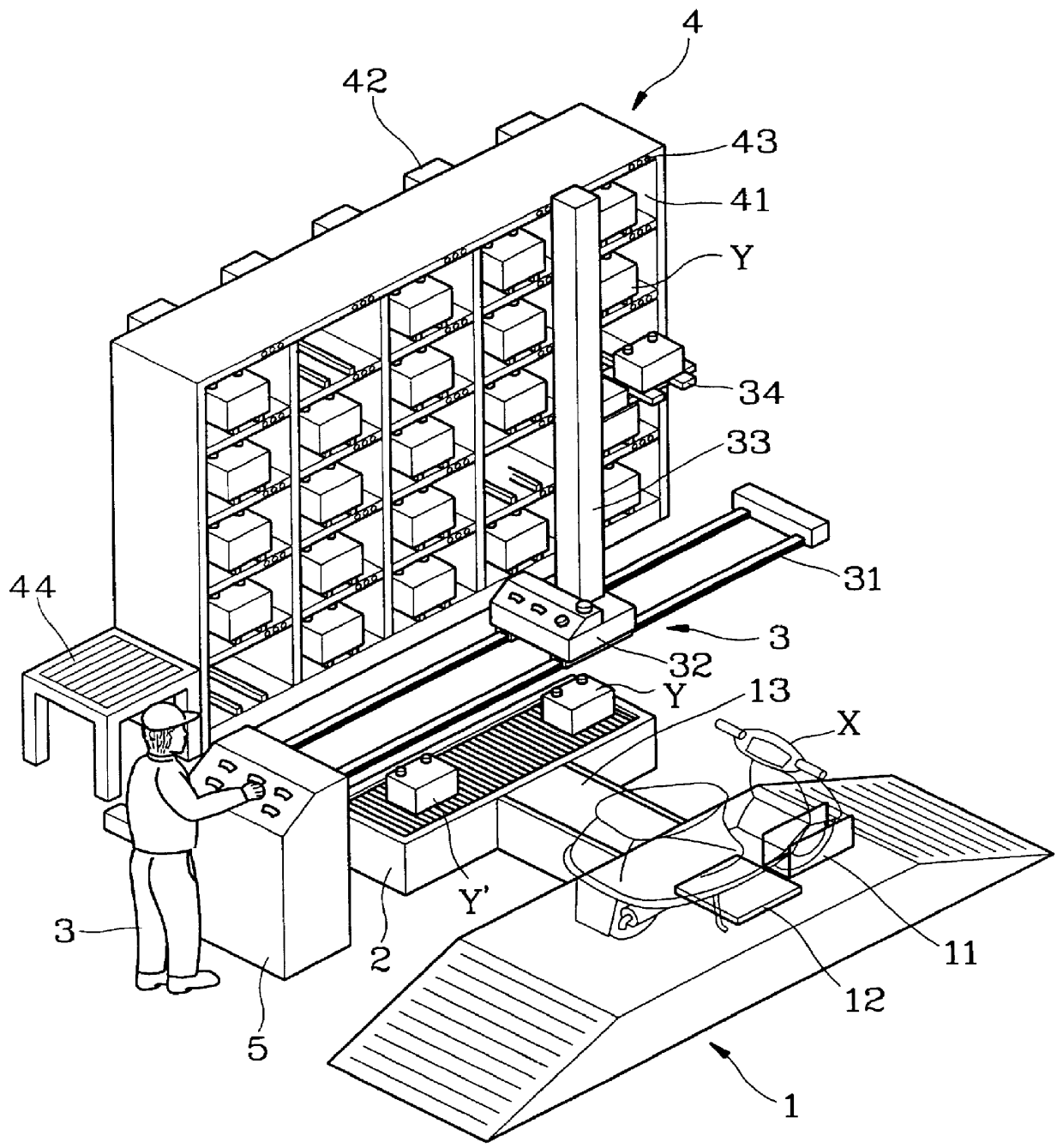
The storage chamber in the first embodiment further comprises one or more battery sensor 42 placed within the room 41 and for detecting the ID code of the battery and managing the charging operation. The sensor 42 is designed to be movable along the stage of the chamber 4 such that one sensor can be shared by multiple rooms. The chamber 4 further comprises a plurality of indicating lamps 43 each arranged within one room 41 to indicate that the room 41 has the charging battery, the most fully-charged battery or the most preferential battery. Moreover, the chamber 4 includes a rejection region 44 for housing the rejected battery.

The access stage 3 in the first embodiment comprises a railway 31 for placing an automatic stage 32 which moves laterally on the railway 31 from one side to another side of the chamber to choose a specific room 41. The railway 31 is further provided with an escalator 33 moving vertically between the top and bottom end of the chamber 4 to select a specific room...

second embodiment

As to the invention, an automatic access means 6 with buffer stage (as shown in FIG. 4) replaces the buffer stage 2 and the access means 3, i.e., integrates the function of the buffer stage 2 and the access means 3 such that the automatic access means 6 can temporarily store both fully and non-fully charged battery without the risk of taking wrong battery.

FIG. 4 shows the second embodiment of the invention, wherein the automatic access means 6 with buffer function is provided. The automatic access means 6 comprises an auto-move stage 62 having moving means such as pulley 622 to move freely between the transfer stage 1 and the storage chamber 4 in order to transfer battery and select a battery room 41, an escalator 63 on the auto-move stage 62 to move vertically between top and bottom end of the storage chamber 4 to select a battery room 41, a store stage 60 beside the escalator 63 to store the battery Y unloaded from the transfer stage 1 and move freely with the auto-move stage 62, ...


PUM

PropertyMeasurementUnit
charging timeaaaaaaaaaa
electrical energyaaaaaaaaaa
flexibleaaaaaaaaaa

Abstract

A selective-type battery charging and transferring system for electric vehicle uses a discretionary scheme rather than conventional continuous scheme and select the fully-charged battery to load on the transfer stage. The electric vehicle can be ensured to load with the most fully charged battery, thus eliminates the difficulty caused by the charging time difference.

Description

The present invention relates to a selective-type battery charging and transferring system for electric vehicle. The inventive system employs discretionary scheme rather than conventional continuous scheme and selects the fully-charged battery to load on the transfer stage, thus eliminates the difficulty caused by the charging time difference.Due to the pollution problem of the petrochemical based system such as pant or vehicle using petroleum, the system powered by electrical energy is become more attractive.However, the present battery for electric vehicle is generally bulky and hard to be carried manually, and the charging of such battery requires long time. Therefore, battery charging and transferring system for electric vehicle is extensively studied.However, in nowadays battery charging and transferring system, the transfer is continuous, i.e., the fully charged battery is sent from convey belt to transfer stage, the non-fully charged battery is sent from transfer stage to the...

Claims


Application Information

Patent Timeline
Patent Type & Authority Patents(United States)
IPC IPC(8): B60S5/06B60S5/00H01M10/42H01M10/44
CPCB60S5/06H01M10/441Y02E60/10
Inventor GU, HUAN-LUNGWEI, TSENG-TEHCHENG, LI-RU
Owner IND TECH RES INST
Why Eureka
Try Eureka